Airy Lite
1 Safety Notices
1.1 Legal Statement
Warning
Unless otherwise stated, all rights (including copyrights, trademarks, patents, trade secrets, and other related rights) in RoboSense's products, technologies, software, programs, data, and other information (including text, icons, photographs, audio, video, graphics, color combinations, layout design, etc.) are owned by RoboSense and its licensors.
No one may use any content contained in this manual in any unauthorized manner without the prior written consent of RoboSense.
The word "RoboSense" and other logos and product and service names are owned by RoboSense. If you need to use them for any advertising or displaying purposes, you must obtain prior written authorization from RoboSense.
1.2 User Guidelines
Please use this product in accordance with the following requirements
- Please strictly abide by relevant national laser safety laws and regulations;
- Please read this product manual in detail before using the product;
- Please use this product only in the relevant field of application;
- Please avoid using this product in environments that are explosive, highly corrosive, or beyond the IP protection level of the equipment.
1.3 Illegal Operation
Please use this product in accordance with the regulations, otherwise it may cause product damage, property loss, and personal injury. Users are responsible for risk arising from unauthorized operations.
- Do not disassemble or modify this product (including accompanying accessories);
- Non-specified power supply and accompanying accessories are prohibited;
- Please avoid abnormal operations such as dropping, colliding, burning, etc.;
- If you notice any damage to the appearance of the device (arc protection cover), please immediately stop using it;
- If you notice any abnormal operation of the product, please immediately stop using it and contact RoboSense in a timely manner.
1.4 Requirements for Operating Personnel
The use of this product requires certain basic professional knowledge and other related requirements for operating personnel. Unreasonable operations performed by personnel without basic knowledge or training do not constitute a fault of RoboSense and may cause damage to equipment and personal property.
- Please read the product manual in detail before using the device;
- Prohibit illegal operations;
- Before working, personnel must undergo training and obtain relevant construction qualifications;
- Have some basic knowledge of computer data connection, electrical, and so on.
1.5 Work Safety and Special Hazards
To avoid risks of accidents, damage to sensor or violating of your product warranty, please read and follow the instructions in this manual carefully before operating the product.
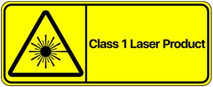
- Laser Safety: This product meets the following standards for laser products: IEC 60825-1:2014;
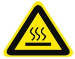
- High Temperature Warning: Please pay attention to the overheating sign on the LiDAR surface to avoid a hot LiDAR surface that may lead to sensor failure or undesirable consequences;
-
Retain Instructions: The safety and operating instructions should be retained for future reference;
-
Heed Warnings: All warnings on the product and in the operating instructions should be adhered to;
-
Servicing: Except for what's described in this manual, the sensor has no field serviceable parts. For servicing, please contact RoboSense sales or the authorized distributors.
2 Product Description
2.1 Product Overview
Airy Lite is a new type of low-cost 3D LiDAR specifically designed by RoboSense to eliminate blind spots. It is primarily used in commercial, industrial, and consumer robotics applications.
Airy Lite features an ultra-short minimum detection distance of 0.1 meters, while offering a wide field of view (FOV) of 360°(H) × 45°(V) and a maximum ranging capability of 60 meters, enabling effective detection of various short-range obstacles over a large area. The entire unit weighs less than 250 grams, with its exposed part boasting a compact structure of only Φ44 × 20mm. This significantly reduces space occupation, allows flexible and convenient installation, and enables easy integration into various devices. Relying on RoboSense's digital platform, it adopts an innovative chip-based transceiver solution, digital architecture, and signal processing technology, achieving high performance while balancing cost optimization and reliability assurance.
2.2 Product Structure
The structure diagram of Airy Lite is shown in Figure 1.
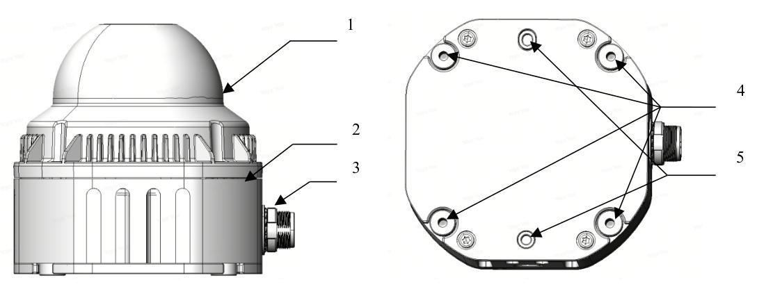
Figure 1 Product Structure Description
It mainly includes the following components:
-
Protective Cover
Both the emitted laser and returned laser need to pass through the specially designed arc-shaped protective cover. Therefore, any obstruction within the laser's field of view (FOV) is strictly prohibited. -
Base
The base unit of Airy Lite incorporates a bottom vent membrane, screw mounting holes, positioning holes, and a cable outlet port. -
Aviation Connector
The electrical interface of the LiDAR. For detailed interface definitions, refer to Section 3.3. -
M3 Screw Mounting Holes
Used to secure the LiDAR to the mounting bracket with M3 screws. -
Mounting Holes
Used to support and fix the position and orientation between the LiDAR and the bracket, and to enhance installation efficiency and accuracy.
For the detailed dimensions and parameters of the above structure, refer to the structural drawing section in Appendix D.
2.3 FOV Distribution
Airy Lite's FOV ranges from 0 to 360° horizontally and from -11.5° to +33.5° vertically, with a vertical angular interval of approximately 1.96°. The correspondence between the 24 channels and the true vertical angles is illustrated in Figure 2.
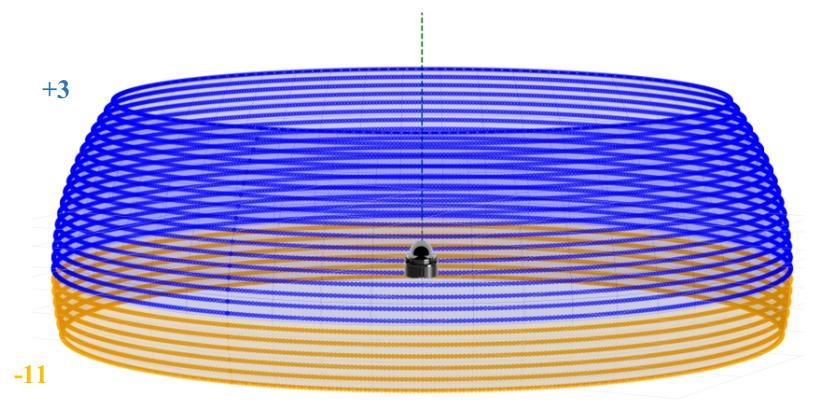
Figure 2 FOV Illustration
Airy Lite's design architecture and scanning sequence result in a point cloud with an approximate 30° gap in every set of 10 frames.
2.4 Specifications1
Table 1 Airy Lite Specifications
| Specifications | |||
|---|---|---|---|
| Number of Channels | 24 | Horizontal Field of View (FOV)2 | 0° ~ 360° |
| Laser Safety Level | Class 1 Eye-Safety | Vertical Field of View (FOV)3 | -11.5° ~ +33.5° |
| Measurement Range4 |
Max Range: 60m Upper/Lower FOV (-11.5° ~ -0.25° & +22.25° ~ +33.5°): 30m@10% NIST Central FOV (-0.25° ~ +22.25°): 40m@10% NIST |
||
| Horizontal Angular Resolution | 0.6° | Vertical Angular Resolution | 1.96° |
| Blind Zone | < 0.1 m | Accuracy (Typical)5 |
7-18 Ch: 0-10m: 0.5cm; 10-40m: 1cm 1-6 & 19-24 Ch: 0-30m: 1cm; 30-40m: 1.5cm |
| Output Points | 144,000 pts / s | Frame Rate | 10 Hz |
| Data Interface | 100Base-Tx | ||
| Output Data Protocol | UDP Packets Over Ethernet | ||
| LiDAR Data Packet Content | Distance, Reflectivity, Timestamp, etc. | ||
| Operating Voltage | 9V - 24V | Return Mode | Single Return: Strongest Return |
| Product Power6 | 6 W | Dimensions (H x W x D) |
65*64*72.5mm (Including cable outlet port) (Protective cover: Φ 44mm*20 mm) |
| Weight | <250g (LiDAR Body) | Operating Temperature7 | -20°C ~ +60°C |
| Time Synchronization | GPS & gPTP & PTP | Storage Temperature | -40°C ~ +85°C |
| Product Model | Airy Lite | Protection Level | IP67 |
1 The following data applies only to mass-produced products. Any samples, prototypes, or other non-mass-produced versions may not be applicable to these specification data. If you have any questions, please contact RoboSense;
2 Approximately one frame out of every 10 point clouds shows a gap of about 30°;
3 The vertical angle exhibits some fluctuation;
4 Test conditions: normal temperature, 100 klux illumination, with a 10% NIST diffuse reflection board as the target;
5 Measurement Accuracy is based on a 50% NIST diffuse reflection target, and the test results are affected by environmental factors, including ambient temperature and target distance. The accuracy value applies to most channels, but variations may exist between certain channels;
6 Device Power Consumption test results are influenced by external environmental factors, including ambient temperature, target distance, and target reflectivity;
7 Device Operating Temperature may be affected by external environmental factors, including lighting conditions and airflow variations.
2.5 Product Principle
2.5.1 Coordinate Mapping
As the LiDAR data packet contains only horizontal rotation angles and distance parameters, to present a three-dimensional point cloud, the polar coordinates (angle and distance) are transformed into Cartesian coordinates \((x, y, z)\) according to the following equations:
where \(r\) is the measured distance, \(\omega\) is the laser's vertical angle, \(\alpha\) is the laser's horizontal rotation angle, \(R\) is the plane radius from the optical center to the origin, \(Z\) is the height from the optical center to the origin, and \(x, y, z\) are the coordinates projected onto the Cartesian \(X, Y, Z\) axes.
2.5.2 Reflectivity Interpretation
Airy Lite LiDAR provides reflectivity information to characterize the reflectance of measured objects. In Airy Lite data, the calibrated reflectivity range is from 1 to 255 (This range is a custom value defined by RoboSense products representing the reflectivity of detected target).
2.5.3 Return Mode
Airy Lite only supports the Strongest Return mode.
2.5.4 Time Synchronization Method
Airy Lite supports three synchronization methods: GPS, PTP (IEEE 1588 V2 protocol), and gPTP (IEEE 802.1AS protocol).
2.5.4.1 GPS Time Synchronization Principle
The GPS module continuously sends GPRMC data and PPS synchronization pulse signals to the product. The PPS pulse length is between 20 and 200 ms. The GPRMC data must be transmitted 10 ms after the falling edge of the PPS synchronization pulse. The timing diagram is shown in Figure 3.
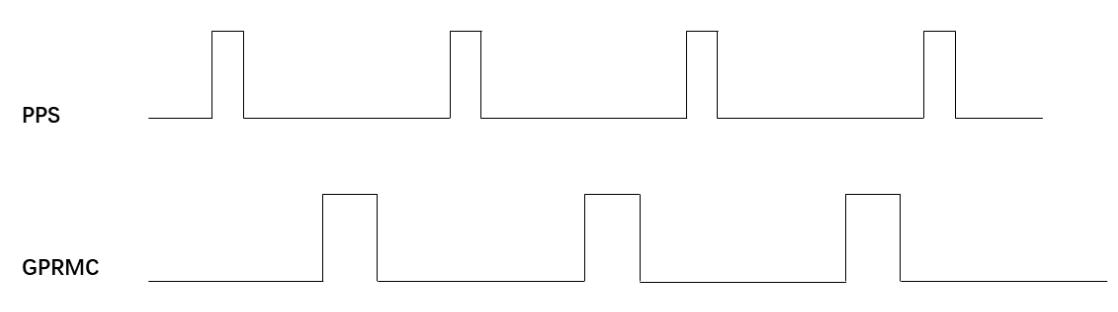
Figure 3 GPS Time Synchronization Timing Diagram
Tip
To ensure the accuracy of time synchronization, set the PPS pulse width between 20 and 200 ms, with a transmission cycle of 1 second. Transmit the PPS pulse first. Use the time information from the subsequent GPRMC data to determine the master time of the previously transmitted PPS pulse.
2.5.4.2 GPS Time Synchronization Usage
The GPS interface of Airy Lite adopts the RS232 protocol. Refer to Table 2 for the pin definition.
Table 2 Product Time Synchronization Pin Definitions
| Communication | Receiving Pin Definition | |
|---|---|---|
| GPS_GPRMC | GPS_PPS | |
| RS232 | RS232 Receives serial data with RS232 electrical level standard output from the GPS module | Receives positive synchronization pulse signal output from the GPS module, with a voltage requirement of 3.3 V |
The external GPS module needs to set the output serial port baud rate to 9600 bps, 8 data bits, no parity bit, and 1 stop bit. Airy Lite only reads GPRMC-formatted data sent by the GPS module. The standard format is as follows:
$ GPRMC,<1>,<2>,<3>,<4>,<5>,<6>,<7>,<8>,<9>,<10>,<11>,<12> * hh
<1> UTC time
<2> Positioning status: A = valid positioning, V = invalid positioning
<3> Latitude
<4> Latitude hemisphere N (Northern Hemisphere) or S (Southern Hemisphere)
<5> Longitude
<6> Longitude hemisphere E (Eastern Longitude) or W (Western Longitude)
<7> Ground speed
<8> Ground course
<9> UTC date
<10> Magnetic declination
<11> Magnetic declination direction: E (East) or W (West)
<12> Mode indication (A = Autonomous positioning, D = Differential, E = Estimated, N = Data invalid)
*hh at the end represents the XOR sum of characters from $ to *
Tip
- The GPS_REC interface specification on the Airy Lite power box is SM2.54 male connector. The pin definitions are shown in Figure 6;
- The interval for sending 1 PPS pulse should be controlled within 1s ± 200 us;
- For years in the range of 00 to 69, they are interpreted as 2000 to 2069; for years in the range of 70 to 99, they are interpreted as 1970 to 1999;
- The status bit in the GPRMC message must be valid for A to allow time synchronization;
- Airy Lite is compatible with most GPRMC message formats from GPS modules available in the market. If any compatibility issues are found during usage, please contact RoboSense.
2.5.4.3 PTP Synchronization Principle
PTP (Precision Time Protocol, IEEE 1588V2 protocol) is a time synchronization protocol used for high-precision time synchronization between devices. It can also be used for frequency synchronization between devices. Compared to various existing time synchronization mechanisms, PTP offers the following advantages:
- Compared to NTP (Network Time Protocol), PTP can meet higher precision time synchronization requirements. NTP generally achieves sub-millisecond level time synchronization accuracy, while PTP can reach sub-microsecond level accuracy;
- Compared to GPS (Global Positioning System), PTP has lower construction and maintenance costs.
2.5.4.4 gPTP Synchronization Principle
gPTP (general Precise Time Protocol, IEEE 802.1AS protocol) is a derivative protocol of PTP in Time-Sensitive Networking (TSN). The synchronization mechanism uses the same P2P peer delay mechanism as the PTP protocol and adopts Ethernet L2 layer communication. Unlike PTP, gPTP requires the use of hardware-based timestamps, i.e., hardware timestamps, so the requirements for switches and master clocks are more stringent, complying with the IEEE 802.1AS protocol.
2.5.4.5 PTP/gPTP Wiring Method
To use PTP/gPTP synchronization, the following preparations are required. Refer to Section 3.4 for connection details:
- Select PTP/gPTP mode in the Web interface. See Section 4.2 for details;
- Ethernet switch;
- Devices that support PTP/gPTP protocols and need time synchronization.
Tip
- The PTP Master device is a third-party device and is not included in the RoboSense shipment. The user needs to purchase it separately;
- RoboSense products, as Slave devices, only receive time from the Master and do not judge the accuracy of the Master's clock source. If there are sudden changes in the time when parsing LiDAR point cloud data, please check if the time provided by the Master is accurate;
- After LiDAR synchronization, when the Master is disconnected, the time in the point cloud data packet will be accumulated based on the LiDAR's internal clock. The time will be reset when the LiDAR is powered off and restarted;
- The LiDAR defaults to gPTP mode. To select PTP/GPS synchronization mode, configuration can be done via the diagnostic protocol. For details on configuring the diagnostic protocol, please contact RoboSense technical support.
3 Product Installation
3.1 Accessory Description
The standard accessories included with Airy Lite LiDAR are listed in Table 3 for reference.
Table 3 Standard Accessory List
| No. | Accessory Name | Specification | Quantity |
|---|---|---|---|
| 1 | LiDAR | Airy Lite | 1 |
| 2 | Screw Pack (optional) | M3 * 8 | 4 |
| 3 | Aviation Connector Cable (optional) | 1.5m | 1 |
| 4 | Power Adapter (optional) | DC12 V * 3.34 A / 40 W | 1 |
| 5 | Power Cable (optional) | 1.2 m | 1 |
| 6 | Ethernet Cable (optional) | 1.5 m | 1 |
| 7 | Product Packing List and Shipment Inspection Report | / | 1 |
Note
For specific requirements, please contact RoboSense or just refer to the commercial agreement.
3.2 Mechanical Installation
The installation diagram of the LiDAR is shown in Figure 4.
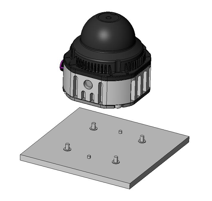
Figure 4 LiDAR Structure Installation Diagram
-
Screw Specifications:
- GB / T70.1, M3 × 8, hex socket cap head, strength grade not lower than 8.8;
-
Installation and Positioning Requirements:
- The bracket and LiDAR are positioned as shown in Figure 4; it is recommended to use the positioning posts on the bottom of the LiDAR for alignment;
- It is recommended to use small bosses near the 4 mounting holes on the bottom bracket to engage with the LiDAR. The overall flatness of the bosses must be within 0.05 mm;
- Use 4 M3 screws to install on the base, 4~5 mm out of the installation surface. Recommended tightening torque is \(6.6 \pm 0.5\) kgf·cm;
- Use 2 \(\Phi\) 2.5 positioning pins on the base for installation alignment, with the height not exceeding \(1.5\mathrm{mm}\) above the installation surface;
- When installing the LiDAR, if both the top and bottom of the LiDAR have contact surfaces, ensure the distance between the surfaces is greater than the height of the LiDAR to avoid compressing it;
- The protective cover is an optical component made of plastic material. During installation or usage, avoid applying force to it;
- As the LiDAR requires a cable harness for external communication, insufficient routing space or an excessively small bending radius will adversely affect the cable's service life and signal quality. The installation requirements for the cable harness are as follows:
- When installing and routing the LiDAR, avoid excessive tension on the connecting cable. Ensure the cable has a certain degree of slack;
- Wire harness diameter is 6mm; with a minimum bending radius of the wire harness of 5 times its diameter.
-
Bracket Stiffness and Strength Requirements:
The mounting bracket must possess sufficient rigidity to securely install and fix the LiDAR, maintaining its stable position under various operating conditions. The design requirements are as follows:
- It is recommended that the LiDAR mounting bracket maintains a certain level of rigidity, with specific boundary requirements determined by user perception-side needs assessment;
- The LiDAR will undergo various random vibrations and mechanical shocks during use. Under these conditions, the bracket needs to withstand significant loads, so it also requires sufficient strength. Under mechanical shock conditions, the maximum stress of the bracket shall be less than 2/3 of the tensile strength. Under random vibration conditions, the 1 sigma RMS stress of the bracket shall be less than 1/5 of the tensile strength.
-
Heat Dissipation Requirements:
Airy Lite may experience moderate temperature rise during operation. Factors such as nearby heat sources, ambient temperature, and solar radiation may exacerbate this condition. RoboSense provides thermal simulation analysis and optimization recommendations based on specific design schemes. General thermal management guidelines include:
- The ambient temperature around the LiDAR must be maintained within its operating temperature range (- \(20^{\circ}C \sim +60^{\circ}C\) );
- The bracket material is recommended to be made of aluminum alloy with a thermal conductivity greater than 90 W/m • K. Some heat dissipation fins should be added to the bracket, with reasonable spacing, height, and direction of the fins to increase the heat dissipation area. The direction should align with the air convection direction for more effective heat dissipation. The bracket surface area shall be no less than 10000 mm \(^{2}\) ;
- Ensure that the LiDAR base or top cover is not covered with non-metallic materials to avoid affecting the overall heat dissipation, leading to excessive temperature rise of the LiDAR;
- It is recommended to add a thermal interface material (with a thermal conductivity of 3W/mK or higher) between the LiDAR base and the underlying metal bracket to improve heat transfer efficiency from the LiDAR to the bracket.
-
Ventilation Requirements:
The Airy Lite base has ventilation holes. The surrounding components of the LiDAR must not obstruct these ventilation holes.
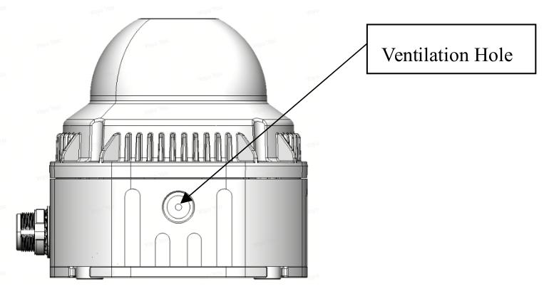
Figure 5 LiDAR Base Ventilation Hole Location Diagram
3.3 Interface Description
3.3.1 Aviation Plug Interface and Definitions
The cable aviation plug on the Airy Lite LiDAR side is shown in Figure 6.
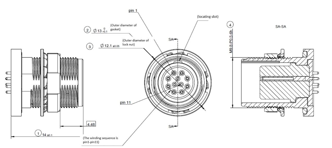
Figure 6 Aviation Plug Interface Pin Numbers
The specific pin definitions of the aviation plug interface on the LiDAR side are shown in Table 4.
Table 4 Aviation Plug Interface Pin Definitions
| Pin No. | Spec | Signal |
|---|---|---|
| 1 | 26AWG | 2P(RX+) |
| 2 | 26AWG | 2N(RX-) |
| 3 | 26AWG | 1P(TX+) |
| 4 | 26AWG | 1N(TX-) |
| 5 | 26AWG | GND |
| 6 | 26AWG | VIN |
| 7 | 26AWG | VIN |
| 8 | 26AWG | GND |
| 9 | 30AWG | GPS PPS |
| 10 | 30AWG | RESERVED |
| 11 | 30AWG | GPS GPRMC |
3.3.2 Interface Cable (Optional)
The optional accessory Interface cable for Airy Lite is shown in the Figure 7 below:
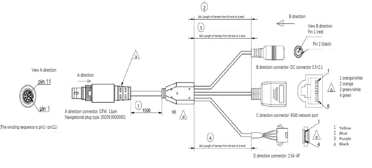
Figure 7 Interface Cable
For detailed specifications of the interfaces on the Interface cable, please refer to Table 5.
Table 5 Interface Cable Interface Specifications
| A End No. | Wire Spec | Wire Definition | A End Color | B End No. | C End No. | D End No. | D End Color |
|---|---|---|---|---|---|---|---|
| 1 | 26AWG | 2P(RX+) | Orange-white | \ | 1 | \ | \ |
| 2 | 26AWG | 2N(RX-) | Orange | \ | 2 | \ | \ |
| 3 | 26AWG | 1P(TX+) | Green-white | \ | 3 | \ | \ |
| 4 | 26AWG | 1N(TX-) | Green | \ | 6 | \ | \ |
| 5 | 26AWG | GND | Black | 2 | \ | \ | \ |
| 6 | 26AWG | VIN | Red | 1 | \ | \ | \ |
| 7 | 26AWG | VIN | Red | 1 | \ | \ | \ |
| 8 | 26AWG | GND | Black | 2 | \ | 4 | Black |
| 9 | 30AWG | GPS PPS | Purple | \ | \ | 3 | Purple |
| 10 | 30AWG | Reserved | Blue | \ | \ | 2 | Blue |
| 11 | 30AWG | GPS GPRMC | Yellow | \ | \ | 1 | Yellow |
3.3.3 Power Interface
The Airy Lite power interface uses a standard DC 5.5 - 2.1 interface.
If the LiDAR motor does not rotate after connecting the power supply, it may be due to a damaged cable. In this case, please contact RoboSense.
3.3.4 RJ45 Ethernet Port
The Airy Lite Ethernet interface follows the EIA/TIA568B standard.
3.3.5 Sync Interface
The Airy Lite sync interface is defined as follows: GPS GPRMC is for GPRMC signal input, and GPS PPS is for PPS signal input.
Info
When connecting the "Ground" of Airy Lite to an external system, the power supply negative pole ("Ground") of the external system and the GPS system's "Ground" must be non-isolated and connected together.
3.4 Quick Connection
The Airy Lite network parameters can be configured, and the default factory setting uses fixed IP and port number mode, as shown in Table 6.
Table 6 Default Factory Network Configuration Table
| Device | IP Address | MSOP Package Port Number |
DIFOP Package Port Number |
IMU Package Port Number |
|---|---|---|---|---|
| Airy Lite | 192.168.1.200 | 6699 | 7788 | 6688 |
| Computer | 192.168.1.102 |
When using the product, the user needs to set the computer's IP address to be in the same subnet as the product, for example, 192.168.1.x (where x can be any value between 1 and 254), and the subnet mask is 255.255.255.0. For unknown product network configuration information, please connect the product and use Wireshark to capture the output package of the product for analysis. The IP configuration and connection methods are as follows:
-
Connecting the LiDAR
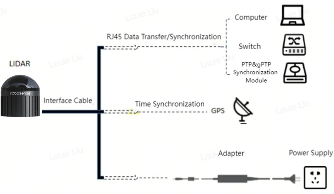
Figure 8 Interface Cable Connection Diagram
The connection method is shown in Figure 8.
- Connect the LiDAR using the aviation plug;
- Connect the PC and LiDAR using the RJ45 Ethernet port;
- After powering on, the LiDAR can work normally.
-
By using Wireshark to capture packets, analyze the ARP messages to perform local IP configuration
-
Perform the following steps after the LiDAR and PC are connected: Start Wireshark (a third-party network analysis tool) and select the correct network interface to begin capturing packet;
-
Use the search box in Wireshark and enter "arp" to search for the mutual addressing packets between the LiDAR and PC, as shown in Figure 9;
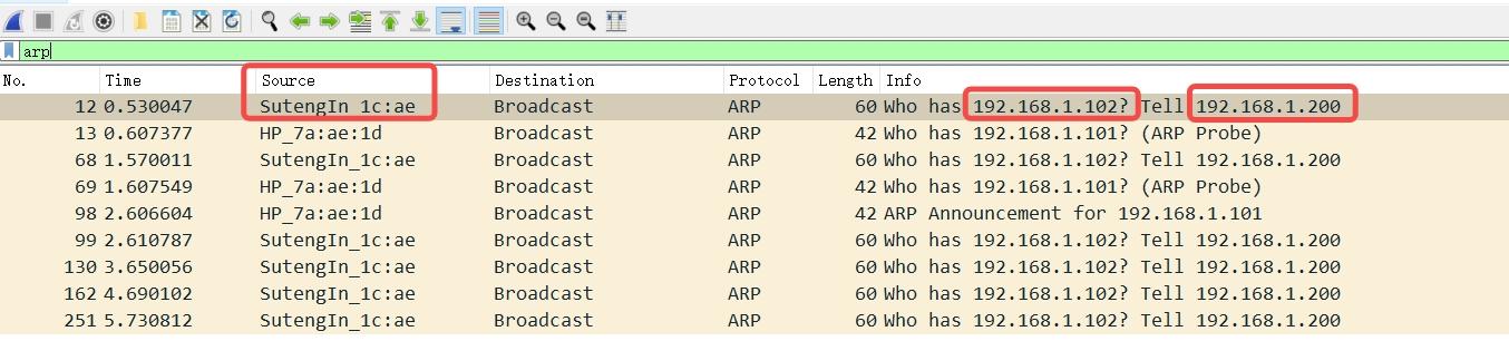
Figure 9 Analyzing ARP Packets
- In Figure 9, the "SutengIn" in the Source column indicates the source information of the LiDAR, indicating that the Source IP is 192.168.1.200, which is the LiDAR's IP. The request is accessing 192.168.1.102, which is the PC's IP. If the local IP is not the requested access IP, then configure the PC's local IP as 192.168.1.102 as shown in step 3. If the access is successful, proceed to step 4.
-
-
Configuring the PC's Local IP
- In the Control Panel, go to "Network and Internet" and then "Network and Sharing Center." In the "View your active networks" section, click on the corresponding Ethernet connection to enter the corresponding "Ethernet Status," and then click on "Properties";
- Double-click "Internet Protocol Version 4 (TCP/IPv4)" to enter the IP information settings and use a static IP for configuration;
- Set the local IP address to 192.168.1.102, subnet mask to 255.255.255.0, and click "OK" to complete the PC's static IP setting.
-
Connection Completed
Tip
- The time synchronization module (PTP & gPTP, GPS time synchronization module) is not included as a standard product. If you need to use these features, please purchase them separately and follow the connection method shown in Figure 8;
- The configuration of the local static IP provided above is only an example for Windows operating systems. For other operating systems, please refer to the actual instructions.
4 Product Usage
4.1 Product Coordinate System
The coordinates and rotation direction of the product are shown in Figure 10.
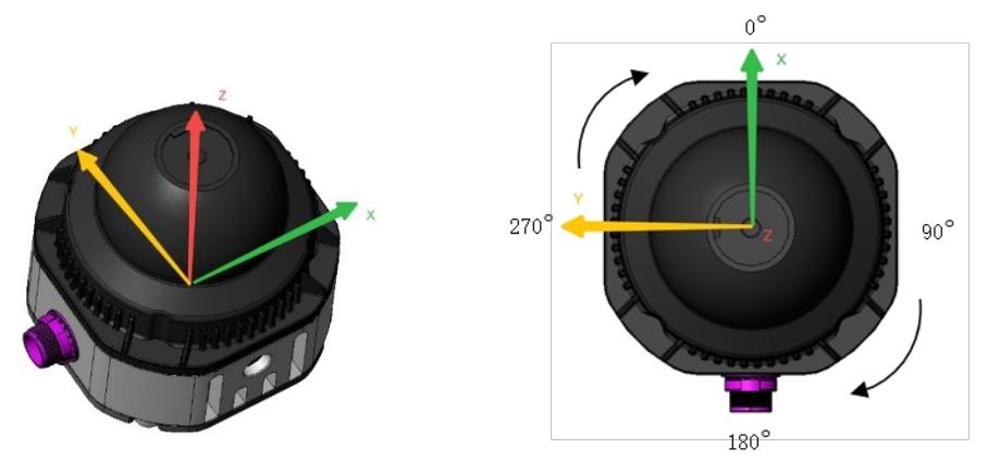
Figure 10 LiDAR Coordinate and Rotation Direction Illustration
Tip
The origin of the coordinates for the LiDAR is defined at the center of the LiDAR base.
4.2 RSView Usage
For data visualization with Airy Lite, you can use free tools such as Wireshark and tcp-dump to obtain raw data. RSView can provide a more convenient way to visualize the raw data.
4.2.1 Software Functions
RSView enables real-time visualization of Airy Lite data. It can also replay data saved in ".pcap" file format, but does not support ".pcapng" files at the moment.
In RSView, the distance measurement values obtained by Airy Lite are displayed as points. It supports various custom colors to display data, such as reflection intensity, time, distance, horizontal angle, and laser beam index. The displayed data can be exported and saved in ".csv" format, and RSView version 3.1.3 and later versions support exporting data in ".las" format.
RSView includes the following features:
- Real-time display of data via Ethernet;
- Save real-time data as PCAP files;
- Replay data from recorded PCAP files;
- Various visualization modes, such as distance, time, horizontal angle, etc;
- Display point data in tabular format;
- Export point cloud data as CSV files;
- Distance measurement tool;
- Display multiple frames of replayed data simultaneously;
- Show or hide individual laser beams from Airy Lite;
- Cropping display.
4.2.2 Installing RSView
RSView can be run on Windows 64-bit and Ubuntu 18.04 or higher operating systems. Please contact RoboSense technical support to obtain the latest version of the Airy Lite RSView software package. The software extraction path should not contain Chinese characters. No installation is required; simply extract the files and run the executable to use the software normally.
4.3 Communication Protocols
Airy Lite uses the UDP protocol, and its output content is primarily divided into two categories. For details, refer to Table 7.
Table 7 Protocol Overview
| Protocol Name | Abbreviation | Function | Packet Size | Send Interval |
|---|---|---|---|---|
| Main data Stream Output Protocol | MSOP | Point Cloud Data | 1280 bytes | Approximately 2.667 ms |
| Device Information Output Protocol | DIFOP | LiDAR Information Output | 540 bytes | Approximately 100 ms |
| IMU Output Protocol | IMU | Inertial Sensor Information | 51 bytes | Approximately 5ms |
Note
- Section 4.3 of the product manual describes and defines the payload of the protocols;
- The Main Data Stream Output Protocol (MSOP) encapsulates the laser scanning data, including distance, angle, and reflection intensity, into packets for output;
- The Device Information Output Protocol (DIFOP) outputs various configuration information about the current state of LiDAR;
- The IMU Output Protocol (IMU) outputs the LiDAR's 6-axis acceleration and angular velocity information;
- This manual does not include descriptions of upgrade or diagnostic protocols. For further information, please contact RoboSense technical support.
4.3.1 Output Data Structure
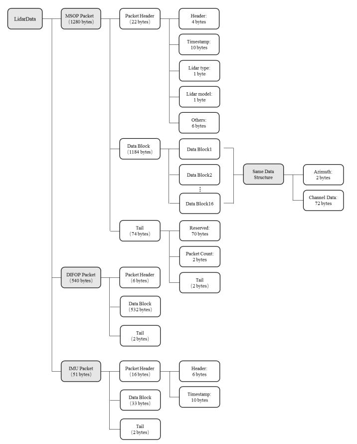
Figure 11 LiDAR Data Structure Diagram
4.3.2 Main Data Stream Output Protocol (MSOP)
Main data Stream Output Protocol, abbreviated as MSOP.
I/O Type: Product output, computer parsing.
4.3.2.1 Header
The frame header (Header) is 22 bytes in total and is used to identify the start position of the data. For details on the data structure, refer to Table 8.
Table 8 MSOP Header Data Table
| Information | Offset | Length (byte) | Description | Total Length (byte) |
|---|---|---|---|---|
| pkt_head | 0 | 4 | 0x5AFF55AA | 22 |
| Reserved | 4 | 1 | ||
| Data Type | 5 | 1 | Value 3, indicating status information | |
| timestamp | 6 | 10 | Timestamp, first 6 bytes indicate seconds, last 4 bytes indicate microseconds | |
| lidar_type | 16 | 1 | 0x0C: Airy Lite Network Platform Edition | |
| lidar_model | 17 | 1 | 0x04: 24 beams | |
| Reserved | 18 | 4 |
Note
The defined timestamp is used to record the system time with a resolution of \(1 \mu s\).
4.3.2.2 Data Block
As shown in Table 9, Data block is the part of sensor measurement value in MSOP package, with a total of 1184 bytes. It consists of 16 data blocks, with each block having a length of 74 bytes.
Each Data block contains 2 bytes for Azimuth, representing horizontal rotation angle information. Each angle information corresponds to 24 channel data.
Table 9 Data Block Definition
| Information | Offset | Length (byte) | Definition | Total Length (byte) |
|---|---|---|---|---|
| Azimuth | 0 | 2 | Horizontal angle in polar coordinates, resolution 0.01 | 74 |
| Channel data 1 | 2 | 2 | Range (Lower 14 bits used for measurement; upper 2 bits reserved for rain, occlusion, and contamination points markers (customer-specific use)) | |
| 4 | 1 | Reflectivity | ||
| Channel data 2 | 5 | 3 | Same as data 1 | |
| Channel data 3 | 8 | 3 | Same as data 1 | |
| ... | ... | ... | ... | |
| Channel data 23 | 68 | 3 | Same as data 1 | |
| Channel data 24 | 71 | 3 | Same as data 1 |
-
Angle Value Definition
In each Block, the angle value output by Airy Lite is the Azimuth angle at which the first channel laser range finding occurs. This angle value is derived from the angle encoder, where the zero position of the angle encoder is the zero point of the angle. The resolution for horizontal rotation angle values is \(0.01^{\circ}\) .
-
Channel Data Definition
Channel data is 3 bytes, with the high two bytes used to represent distance information and the low one byte used to represent reflectivity information, as shown in Table 10.
Table 10 Channel Data
| Channel Data (3 bytes) | |
|---|---|
| 2 bytes Distance | 1 byte Reflectivity |
| Lower 14 bits for data, upper 2 bits reserved for rain, occlusion, and contamination points markers | Reflectivity |
Note
Distance is 2 bytes, resolution is 0.5 cm.
4.3.2.3 Tail
Frame tail (Tail) is 74 bytes in total, consisting of two parts: 2 bytes of fixed characters for Tails and 72 bytes of reserved space.
4.3.3 Device Info Output Protocol (DIFOP)
Device Info Output Protocol, abbreviated as DIFOP.
I/O Type: Product output, computer parsing.
DIFOP is an "output-only" protocol designed to periodically send information such as product serial number (S/N), firmware version, calibration angles, and operational status, etc. to the user. By reading the DIFOP, users can interpret specific parameters of the product in use.
A complete DIFOP packet has a data format structure of DIFOP header, data area, and tail. Every packet has 540 bytes totally. The basic structure of the data packet is shown in Table 11.
Table 11 Data Format Structure of DIFOP Packet
| Information | Offset | Length (byte) | Description |
|---|---|---|---|
| pkt_head | 0 | 4 | Packet Start Flag Fixed Value: 0x5A 0xFF 0x55 0xAA |
| Reserved | 4 | 1 | |
| Data Type | 5 | 1 | Value 3, indicating status information |
| Mainboard Firmware Version | 6 | 4 | Appendix B.1 |
| Baseboard Firmware Version | 10 | 4 | Appendix B.2 |
| Motor Firmware Version | 14 | 4 | Appendix B.3 |
| Ethernet Source IP Address | 18 | 4 | Appendix B.4 |
| Ethernet Destination IP Address | 22 | 4 | |
| LiDAR MAC Address | 26 | 6 | |
| MSOP Port | 32 | 2 | |
| DIFOP Port | 34 | 2 | |
| IMU Port Number | 36 | 2 | |
| Reserved | 38 | 10 | |
| Reserved | 48 | 1 | |
| Product SN Number | 49 | 6 | Appendix B.5 |
| Reserved | 55 | 39 | |
| Time Sync Mode Setting | 94 | 1 | Appendix B.6 |
| Time Sync Status | 95 | 1 | |
| Time | 96 | 10 | Appendix B.7 |
| GPRMC Baud Rate in GPS Synchronization Mode (default baud rate is 9600) | 106 | 1 | The baud rate values are as follows: 0x00: 1200 0x01: 2400 0x02: 4800 0x03: 9600 0x04: 14400 0x05: 19200 0x06: 38400 0x07: 43000 0x08: 57600 0x09: 76800 0x0A: 115200 0x0B: 128000 0x0C: 230400 0x0D: 256000 0x0E: 460800 0x0F: 921600 0x10: 1382400 |
| Reserved | 107 | 204 | |
| FOV Start Angle | 311 | 2 | The range is 0-359, the precision is $0.01^{\circ}$ |
| FOV End Angle | 313 | 2 | The range is 0-359, the precision is $0.01^{\circ}$ |
| Phase-Locked Angle | 315 | 2 | The range is 0-360, the precision is $1^{\circ}$ |
| Reserved | 317 | 25 | |
| Real-time Motor Speed | 342 | 2 | Appendix B.8 |
| Reserved | 344 | 4 | |
| Vertical Angle Calibration | 348 | 48 | Appendix B.9 |
| Vertical Angle Calibration Positive/Negative Sign | 396 | 3 | |
| Horizontal Angle Calibration | 399 | 48 | Appendix B.10 |
| Horizontal Angle Calibration Positive/Negative Sign | 447 | 3 | |
| Reserved | 450 | 23 | |
| IMU Extrinsic Calibration Data | 473 | 4 | Appendix B.11 |
| 477 | 4 | ||
| 481 | 4 | ||
| 485 | 4 | ||
| 489 | 4 | ||
| 493 | 4 | ||
| 497 | 4 | ||
| Reserved | 501 | 35 | |
| Mainboard Total Input Voltage | 508 | 2 | Appendix B.12 |
| Reserved | 510 | 16 | |
| Baseboard External Power Supply Input Voltage | 526 | 2 | Appendix B.13 |
| Reserved | 528 | 10 | |
| Frame Tail | 538 | 2 | 0x0F 0xF0 |
Note
- The Header (DIFOP Identification Header) consists of the bytes 0x5A, 0xFF, 0x55, 0xAA, and can be used as a check sequence for the packet;
- The Tail contains the bytes 0x0F, 0xF0;
- The definition and usage of each item's registers can be found in detail in Appendix B of the product manual. The corresponding relationship is specified in the Remarks column of Table 11.
4.3.4 IMU Data Stream Output Protocol
I/O Type: Product output, computer parsing.
The IMU output is the attitude information of IMU in the product, which can be used to adjust the external parameters of the customer's products. Each packet contains 51 bytes. The basic structure of the packet is shown in Table 12.
Table 12 IMU Data Format Structure
| Information | Offset | Length (byte) | Remarks |
|---|---|---|---|
| IMU Header | 0 | 4 | 0x5A 0xFF 0x55 0xAA |
| Reserved | 4 | 1 | |
| Data Type | 5 | 1 | Value 2, indicating IMU data |
| timestamp | 6 | 10 | UTC time format. The first 6 bytes are second timestamps, and the last 4 bytes are microsecond timestamps. |
| AccelX | 16 | 4 | X-axis acceleration value, float, unit: $m/s^2$ |
| AccelY | 20 | 4 | Y-axis acceleration value, float, unit: $m/s^2$ |
| AccelZ | 24 | 4 | Z-axis acceleration value, float, unit: $m/s^2$ |
| GyroX | 28 | 4 | X-axis angular velocity, float, unit: rad/s |
| GyroY | 32 | 4 | Y-axis angular velocity, float, unit: rad/s |
| GyroZ | 36 | 4 | Z-axis angular velocity, float, unit: rad/s |
| Internal Temperature | 40 | 4 | IMU internal temperature (-40~105°C), signed, resolution: 0.01° |
| ODR | 44 | 1 |
Data Output Frequency 0: 25Hz 1: 50Hz 2: 100Hz 3: 200Hz (Default Value) |
| AccelFsr | 45 | 1 |
Accelerometer Range 0: +/- 2g 1: +/- 4g (Default Value) 2: +/- 8g 3: +/- 16g |
| GyroFsr | 46 | 1 |
Gyroscope Range 0: +/- 250 dps 1: +/- 500 dps (Default Value) 2: +/- 1000 dps 3: +/- 2000 dps |
| Packet Count | 47 | 2 | Packet Sequence Number u16 0~0xFFFF |
| Tails | 49 | 2 | CRC16 (calculated from pkt_head to packet count section) |
5 Fault Diagnosis
This chapter lists some common problems encountered during the use of the product and their corresponding troubleshooting methods. For details, refer to Table 13.
Table 13 Common Fault Troubleshooting Methods
| Fault Phenomenon | Solution |
|---|---|
| The Product Motor Does Not Rotate | Check whether the connector cable on the aviation plug power/product side is loose or if the wiring harness is damaged. |
| The Product Keeps Restarting During Startup |
1. Check the input power connection and polarity; 2. Check if the voltage and current of the input power meet the requirements; 3. Check if the installation plane of the product is level or if the screws on the bottom of the LiDAR are tightened too tightly. |
| The Product Internally Rotates, But There Is No Data |
1. Check if the LiDAR emits light normally; 2. Check if the network connection is normal; 3. Confirm if the computer-side network configuration is correct; 4. Use other software (such as Wireshark) to check if the data is received; 5. Disable the firewall and other security software that may block the network; 6. Check if the power supply is normal; 7. Try restarting the product. |
| Wireshark Can Receive Data, But RSView Does Not Display Point Cloud |
1. Close the computer's firewall and run RSView through the firewall; 2. Confirm that the computer's IP configuration matches the destination address set in the product; 3. Confirm that the Sensor Network Configuration in RSView is set correctly; 4. Confirm that the installation directory or configuration file storage directory of RSView does not contain any Chinese characters; 5. Confirm that the data packets received by Wireshark are of the MSOP type. |
| The Product Has Frequent Data Loss |
1. Confirm if there is a large number of other network packets or network conflicts in the network; 2. Confirm if there are other network products sending a large amount of data in broadcast mode, causing sensor data blocking; 3. Confirm if the computer's performance and interface performance meet the requirements; 4. Remove all other network products and directly connect to the computer to confirm if data loss occurs. |
| Unable to Synchronize GPS/PTP/gPTP Time |
1. Confirm if the synchronization mode has been switched to the correct mode on the web page; 2. Under the GPS time synchronization mode: - Confirm if the GPS module's baud rate is 9600 bps, 8 data bits, no parity bit, and 1 stop bit; - Confirm if the GPS module outputs 3.3V TTL or RS232 level; - Confirm if the 1PPS pulse is continuous and the wiring is correct; - Confirm if the NMEA message format of GPRMC is correct; - Confirm if the GPS module and interface box share the same ground; - Confirm if the GPS module receives a valid fix; - Confirm if the GPS module is validly positioned (outdoors); 3. Under the PTP / gPTP time synchronization mode: - Confirm if the PTP / gPTP Master synchronization protocol complies with the current PTP / gPTP protocol; - Confirm if the PTP / gPTP Master is working properly. |
| No Data Output After Passing Through The Router | Close the DHCP function of the router or set the IP address of the sensor to the correct IP address internally in the router. |
| ROS Driver Displays A Fixed Blank Area Rotating When Showing Point Cloud | This phenomenon is normal. It occurs because the ROS driver splits the data into fixed packages for frame display. The blank part of the data will be displayed in the next frame. |
| RSView Software Outputs Point Clouds As A Single Ray | For Windows 10 systems, set RSView to run in Windows 7 compatibility mode to resolve the issue. |
6 Product Maintenance
6.1 Transportation and Logistics
Improper transportation can cause product damage
- The product should be packaged with shockproof and moisture-proof materials to avoid damage during transportation. It is recommended to use the original packaging;
- Handle with care during transportation to avoid impact or dropping;
- When receiving the goods, carefully check the delivery list for any damages (including the product and packaging);
- If there is any transportation damage, refuse to accept the delivery and contact RoboSense promptly.
6.2 Storage
Improper storage may cause product damage
- Store the product in an indoor environment with normal temperature and dry conditions;
- Handle the product gently to avoid impact or dropping;
- The product should be stored in a safe environment to avoid corrosion, mechanical impact, or exposure to environments exceeding the protection level;
- Regularly inspect the condition of all components and packaging, and it is recommended to check every three months.
6.3 Product Cleaning
To ensure accurate perception of the surrounding environment, keep the RS-LiDAR's circular protective cover clean.
6.3.1 Precautions
Note
- Before cleaning the RS-LiDAR, carefully read and understand the content of this section. Improper cleaning may damage the product.
- When using the LiDAR in harsh environmental conditions, clean the surface regularly to keep the LiDAR clean. Otherwise, it may affect the normal operation of the LiDAR.
6.3.2 Required Materials
- Clean and dust-free cloth;
- Neutral solution at moderate temperature (such as soapy water, distilled water, 99% concentration of ethanol, etc.).
6.3.3 Cleaning Method
-
If the LiDAR surface is only covered with some dust:
- Use a clean and dust-free cloth, dip it in a small amount of neutral solution;
- Gently wipe the LiDAR surface;
- Dry it with a clean and dry dust-free cloth.
-
If the LiDAR surface is covered with mud or other solid foreign objects:
- First, spray clean water on the dirty part of the LiDAR surface to remove the mud or foreign objects (Note: Do not directly wipe off the mud with a dust-free cloth, as it may scratch the surface, especially the protective cover);
- Then spray warm soapy water on the dirty part. The lubricating effect of the soapy water helps to remove the foreign objects. Gently wipe the LiDAR surface with a fiber cloth, but be careful not to scratch the surface;
- Finally, rinse off the residual soap on the LiDAR surface with clean water (if there is still residue, clean it again with 99% ethanol) and dry it with a clean and dry dust-free cloth.
7 After-sales Service
If the solutions provided in Chapter 6 of the troubleshooting guide do not solve the problem, please promptly contact RoboSense.
Official Website: https://www.robosense.cn/en/contact
Email: support@robosense.cn
Phone: +86-0755-86325830 / +86-15338772453
Info
- Please wait for a confirmation response from RoboSense after-sales service before sending the product back;
- When sending the product back, please use the original packaging or an equivalent cushioned and moisture-resistant packaging.
Appendix A ROS & ROS2 Package
rslidar_sdk is the driver SDK for ROS platform. Please download it from RoboSense homepage on github or contact RoboSense to obtain it.
- rslidar_sdk relies on rs_driver, which is the basic driver of RoboSense. Download rs_driver from github;
- If ROS2 is used, rslidar_sdk also relies on rslidar_msg, which is the msg definition file, which can be downloaded from github;
- The driver SDK download package contains rich usage guidelines. Please read the README file and doc folder in the file before using the driver SDK.
Tip
- SDK address: https://github.com/RoboSense-LiDAR/rsLiDAR_sdk
- rs_driver address: https://github.com/RoboSense-LiDAR/rs_driver
- msg address: https://github.com/RoboSense-LiDAR/rslidar_msg
Appendix B DIFOP Data Definitions
This appendix supplements the definitions of each item in the DIFOP protocol outlined in Section 4.3.3, facilitating user understanding for product use and development. For calculations, big-endian mode is used, and "Value" represents the decimal number derived from the corresponding offset bytes.
B.1 Mainboard Firmware Version
TOP_FRM
Table 14 Mainboard Firmware Version
| Mainboard Firmware Version (4 bytes) | ||||
|---|---|---|---|---|
| No. | byte 1 | byte 2 | byte 3 | byte 4 |
| Fun. | TOP_FRM | |||
Register Description
- This register is used to read the mainboard firmware version number;
- For example, if byte 1 = 0x00, byte 2 = 0x10, byte 3 = 0x04, byte 4 = 0x0c, and byte 5 = 0x00, then the firmware version number is: 00 10 04 0c.
B.2 Baseboard Firmware Version
BOT_FRM
Table 15 Baseboard Firmware Version
| Baseboard Firmware Version (4 bytes) | ||||
|---|---|---|---|---|
| No. | byte 1 | byte 2 | byte 3 | byte 4 |
| Fun. | BOT_FRM | |||
Register Description
- This register is used to read the baseboard firmware version number;
- For example, if byte 1 = 0x00, byte 2 = 0x10, byte 3 = 0x04, byte 4 = 0x0c, then the firmware version number is: 00 10 04 0c.
B.3 Motor Firmware Version
MOT_FRM
Table 16 Motor Firmware Version
| Motor Firmware Version (4 bytes) | ||||
|---|---|---|---|---|
| No. | byte 1 | byte 2 | byte 3 | byte 4 |
| Fun. | MOT_FRM | |||
Register Description
- This register is used to read the motor firmware version number;
- For example, if byte 1 = 0x00, byte 2 = 0x24, byte 3 = 0x12, byte 4 = 0x12, then the firmware version number is: 00 24 12 12.
B.4 Ethernet
ETH
Table 17 Ethernet
| Register of Ethernet (30 bytes) | ||||||||
|---|---|---|---|---|---|---|---|---|
| No. | byte 1 | byte 2 | byte 3 | byte 4 | byte 5 | byte 6 | byte 7 | byte 8 |
| Fun. | LIDAR_IP | DEST_PC_IP | ||||||
| No. | byte 9 | byte 10 | byte 11 | byte 12 | byte 13 | byte 14 | byte 15 | byte 16 |
| Fun. | MAC_ADDR | MSOP | ||||||
| No. | byte 17 | byte 18 | byte 19 | byte 20 | byte 21 | byte 22 | byte 23 | byte 24 |
| Fun. | DIFOP | IMU | RESERVED | |||||
| No. | byte 25 | byte 26 | byte 27 | byte 28 | byte 29 | byte 30 | \ | \ |
| Fun. | RESERVED | \ | ||||||
Register Description
- LiDAR_IP is the source IP address of the LiDAR, occupying 4 bytes;
- DEST_PC_IP is the destination PC's IP address, occupying 4 bytes;
- MAC_ADDR is the MAC address of the LiDAR;
- MSOP, DIFOP and IMU each occupies 2 bytes, and the source and destination port numbers are required to be identical.
B.5 Product Serial Number
Table 18 Serial Number Information
| Serial Number (6 bytes) | ||||||
|---|---|---|---|---|---|---|
| No. | byte 1 | byte 2 | byte 3 | byte 4 | byte 5 | byte 6 |
| Fun. | SN | |||||
Register Description
- This register is used for the device serial number;
- Similar to a MAC address, it consists of 6 bytes, representing the product serial number in hexadecimal.
B.6 Time Sync Mode Setting
TIME_SYNC_INFO
Table 19 Time Sync Information
| Time Sync Information (2 bytes) | ||
|---|---|---|
| No. | byte 1 | byte 2 |
| Fun. | Time_Sync_Mode | Time_Sync_State |
Register Description
- This register is used to read time synchronization information;
- Byte 1 is the time synchronization mode status bit, defined as follows:
- 0x00: GPS
- 0x01: E2E-L4
- 0x02: P2P
- 0x03: gPTP
- 0x04: E2E-L2
- Byte 2 is the time synchronization success status bit, defined as follows:
- 0x00: Not synchronized
- 0x01: Synchronized successfully
B.7 Time
UTC_TIME
Table 20 Time Information
| Register of Time (10 bytes) | ||||||||||
|---|---|---|---|---|---|---|---|---|---|---|
| No. | byte 1 | byte 2 | byte 3 | byte 4 | byte 5 | byte 6 | byte 7 | byte 8 | byte 9 | byte 10 |
| Fun. | sec | μs | ||||||||
Register Description
- This register is used to read time information;
- The range of the microsecond (μs) value: 0 ~ 999,999.
B.8 Real-time Motor Speed
REALTIME_ROTATION_SPEED
Table 21 Real-time Motor Speed
| Real-time Motor Speed (2 bytes) | ||
|---|---|---|
| No. | byte 1 | byte 2 |
| Fun. | REALTIME_ROTATION_SPEED | |
Register Description
- This register is used to read the real-time speed value of the motor, with the unit being 0.1 RPM;
- For example, if byte 1 = 0x17 and byte 2 = 0x70, then Value = 6000. The real-time speed is calculated as \(6000 \times 0.1\) RPM = 600 RPM.
B.9 Vertical Angle Calibration Sign Bits
Table 22 Vertical Angle Calibration Bits
| Vertical Angle Calibration Register (48 bytes) | ||||||||
|---|---|---|---|---|---|---|---|---|
| No. | byte 1 | byte 2 | byte 3 | byte 4 | byte 5 | byte 6 | byte 7 | byte 8 |
| Fun. | Channel 1 Vertical Angle | Channel 2 Vertical Angle | Channel 3 Vertical Angle | Channel 4 Vertical Angle | ||||
| No. | ... | |||||||
| Fun. | ... | |||||||
| No. | byte 41 | byte 42 | byte 43 | byte 44 | byte 45 | byte 46 | byte 47 | byte 48 |
| Fun. | Channel 21 Vertical Angle | Channel 22 Vertical Angle | Channel 23 Vertical Angle | Channel 24 Vertical Angle | ||||
Table 23 Vertical Angle Calibration Sign Bits
| Vertical Angle Calibration Sign Bit Register (3 bytes) | |||
|---|---|---|---|
| No. | byte 1 | byte 2 | byte 3 |
| Fun. | Sign Bits Corresponding to 24-Channel Vertical Angles | ||
Register Description
- The vertical calibration angle for each channel must be calculated by combining the Vertical Angle Calibration value with the Vertical Angle Calibration Sign Bits;
- As shown in Table 22, the vertical angle value for each channel is represented by 2 bytes, with an angular resolution of \(0.01^{\circ}\);
- As shown in Table 23, the 24 channels collectively use 3 bytes (24 bits) to represent the sign bits of each channel. Each bit indicates the sign of the vertical calibration angle for the corresponding channel (0 for positive, 1 for negative). Bit 1 of Byte 1 corresponds to Channel 1, Bit 2 of Byte 1 corresponds to Channel 2, etc.;
- Example: For Channel 1 in Table 22, the register value is Byte 1 = 0x01, Byte 2 = 0x71. Converted to decimal, this gives 369. Multiplying by the angular resolution yields \(3.69^{\circ}\). Meanwhile, in Table 23, the sign bit for Channel 1 is Bit 1 of Byte 1, with a value of 0 indicating a positive sign. Therefore, the vertical angle value for Channel 1 is \(+3.69^{\circ}\).
B.10 Horizontal Angle Calibration and Horizontal Angle Calibration Sign Bits
Table 24 Horizontal Angle Calibration Bits
| Horizontal Angle Calibration Register (48 bytes) | ||||||||
|---|---|---|---|---|---|---|---|---|
| No. | byte 1 | byte 2 | byte 3 | byte 4 | byte 5 | byte 6 | byte 7 | byte 8 |
| Fun. | Channel 1 Horizontal Angle | Channel 2 Horizontal Angle | Channel 3 Horizontal Angle | Channel 4 Horizontal Angle | ||||
| No. | ... | |||||||
| Fun. | ... | |||||||
| No. | byte 41 | byte 42 | byte 43 | byte 44 | byte 45 | byte 46 | byte 47 | byte 48 |
| Fun. | Channel 21 Horizontal Angle | Channel 22 Horizontal Angle | Channel 23 Horizontal Angle | Channel 24 Horizontal Angle | ||||
Table 25 Horizontal Angle Calibration Sign Bits
| Horizontal Angle Calibration Sign Bits Register (3 bytes) | |||
|---|---|---|---|
| No. | byte 1 | byte 2 | byte 3 |
| Fun. | Sign Bits Corresponding to 24-Channel Horizontal Angles | ||
Register Description
- The calculation method for horizontal angle calibration is the same as that for vertical angle calibration. For details, refer to Appendix B.9.
B.11 IMU Calibration Data
Table 26 IMU Data
| IMU Calibration Data (28 bytes) | ||||||||
|---|---|---|---|---|---|---|---|---|
| No. | byte 1 | byte 2 | byte 3 | byte 4 | byte 5 | byte 6 | byte 7 | byte 8 |
| Fun. | q_x | q_y | ||||||
| No. | byte 9 | byte 10 | byte 11 | byte 12 | byte 13 | byte 14 | byte 15 | byte 16 |
| Fun. | q_z | q_w | ||||||
| No. | byte 17 | byte 18 | byte 19 | byte 20 | byte 21 | byte 22 | byte 23 | byte 24 |
| Fun. | x | y | ||||||
| No. | byte 25 | byte 26 | byte 27 | byte 28 | ||||
| Fun. | z | |||||||
Register Description
- The register is used to read the calibration data of the IMU relative to the LiDAR coordinate system;
- This calibration data includes pose estimation and position offset, and the data type is 32-bit float (conforming to the IEEE 754 standard);
-
For example, the current bytes of x (byte 17~byte 20) are 3b 8b 43 96, and its calculation method is as follows:
a. First, combine the four bytes into 32 binary numbers, that is, 00111011 10001011 01000011 10010110;
b. Separate the sign bit, the exponent field and the mantissa field. Among them, the sign bit is 31 bits, that is, 0, the exponent field is 23 to 30 bits, that is, 01110111, and the mantissa field is 0 to 22 bits, that is, 00010110100001110010110;
c. Calculate the values of each domain, according to IEEE 754. Here, the sign domain is 0, indicating a positive number. The exponent domain is 01110111, which converts to 119 in decimal, and the actual exponent is \(119 - 127 = -8\). The mantissa domain is 00010110100001110010110. Therefore, it is first converted to a decimal fraction, approximately 0.086. The actual mantissa calculation is: \(1 + 0.086 = 1.086\);
d. Floating-point number, using the formula: \(\text{Float32} = (-1)^{\text{sign domain}} \times \text{mantissa domain} \times 2^{\text{exponent domain}} = (-1)^{0} \times 1.086 \times 2^{-8} = 0.00424\).
B.12 Mainboard Input Voltage
MAINBOARD_VOLTAGE
Table 27 Mainboard Input Voltage
| Mainboard Input Voltage (2 bytes) | ||
|---|---|---|
| No. | byte 1 | byte 2 |
| Fun. | Mainboard Voltage | |
Register Description
- This register is used to read the mainboard input voltage of the device;
- Unit: V. The voltage value consists of 2 bytes. The calculation formula is: Mainboard Voltage = Value / 100.
B.13 Baseboard External Power Supply Input Voltage
VOLTAGE_BOT_BUS
Table 28 Baseboard External Power Supply Input Voltage
| Baseboard External Power Supply Input Voltage (2 bytes) | ||
|---|---|---|
| No. | byte 1 | byte 2 |
| Fun. | Machine Voltage | |
Register Description
- This register is used to read the Baseboard External Power Supply Input Voltage of the device;
- Unit: V. The voltage value consists of 2 bytes. The calculation formula is: Mainboard Voltage = Value / 100.
Appendix C Structural Drawings
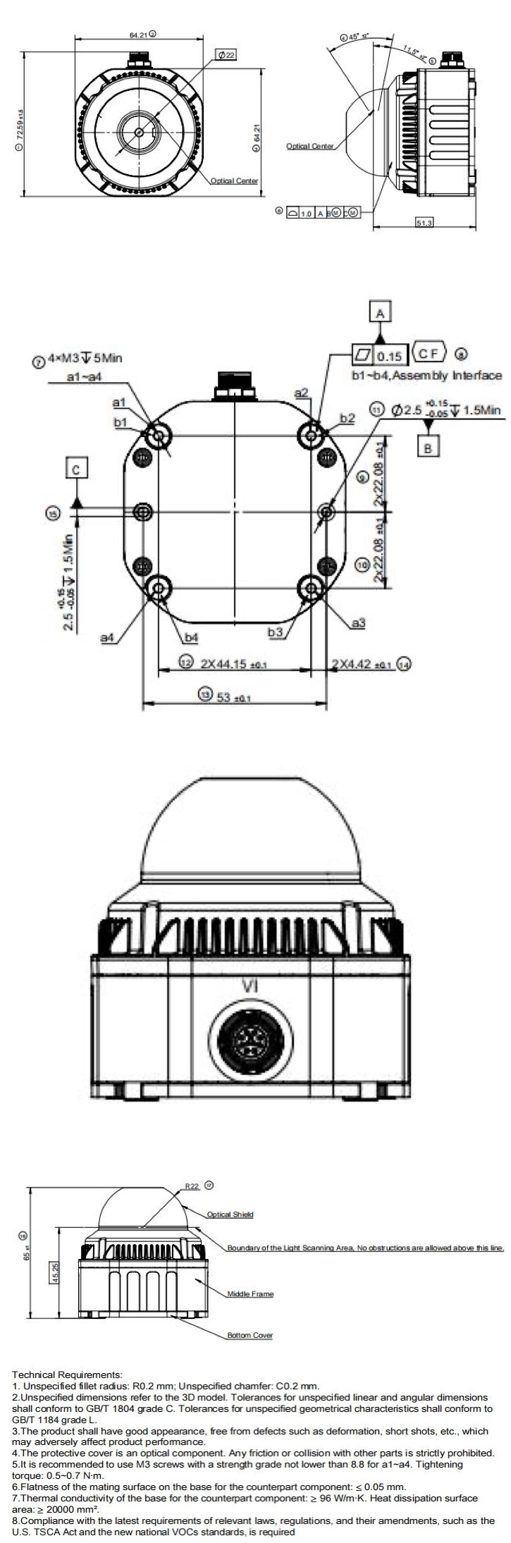
Appendix D Emission Delay Table per Channel
Table 29 Emission Delay Table per Channel
| Channel Number | Emission Delay (μs) | Channel Number | Emission Delay (μs) |
|---|---|---|---|
| 00-05 | 0 | 12-17 | 64 |
| 06-11 | 21 | 18-23 | 107 |