E1R
1 Safety Notices
1.1 Legal Statement
Warning
Unless otherwise stated, all rights (including copyrights, trademarks, patents, trade secrets, and other related rights) in RoboSense's products, technologies, software, programs, data, and other information (including text, icons, photographs, audio, video, graphics, color combinations, layout design, etc.) are owned by RoboSense and its licensors.
No one may use any content contained in this manual in any unauthorized manner without the prior written consent of RoboSense.
The word "RoboSense" and other logos and product and service names are owned by RoboSense. If you need to use them for any advertising or displaying purposes, you must obtain prior written authorization from RoboSense.
1.2 User Guidelines
Please use this product in accordance with the following requirements
- Please strictly abide by relevant national laser safety laws and regulations;
- Please read this product manual in detail before using the product;
- Please use this product only in the relevant field of application;
- Please avoid using this product in environments that are explosive, highly corrosive, or beyond the IP protection level of the equipment.
1.3 Illegal Operation
Please use this product in accordance with the regulations, otherwise it may cause product damage, property loss, and personal injury. Users are responsible for risk arising from unauthorized operations.
- Do not disassemble or modify this product (including accompanying accessories);
- Non-specified power supply and accompanying accessories are prohibited;
- Please avoid abnormal operations such as dropping, colliding, burning, etc.;
- If you notice any damage to the appearance of the device (arc protection cover), please immediately stop using it;
- If you notice any abnormal operation of the product, please immediately stop using it and contact RoboSense in a timely manner.
1.4 Requirements for Operating Personnel
The use of this product requires certain basic professional knowledge and other related requirements for operating personnel. Unreasonable operations performed by personnel without basic knowledge or training do not constitute a fault of RoboSense and may cause damage to equipment and personal property.
- Please read the product manual in detail before using the device;
- Prohibit illegal operations;
- Before working, personnel must undergo training and obtain relevant construction qualifications;
- Have some basic knowledge of computer data connection, electrical, and so on.
1.5 Work Safety and Special Hazards
To avoid risks of accidents, damage to sensor or violating of your product warranty, please read and follow the instructions in this manual carefully before operating the product.
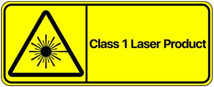
- Laser Safety: This product meets the following standards for laser products: IEC 60825-1:2014;
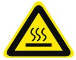
- High Temperature Warning: Please pay attention to the overheating sign on the LiDAR surface to avoid a hot LiDAR surface that may lead to sensor failure or undesirable consequences;
-
Retain Instructions: The safety and operating instructions should be retained for future reference;
-
Heed Warnings: All warnings on the product and in the operating instructions should be adhered to;
-
Servicing: Except for what's described in this manual, the sensor has no field serviceable parts. For servicing, please contact RoboSense sales or the authorized distributors.
2 Product Description
2.1 Product Structure
The shape and size diagram of E1R is shown in Figure 1.
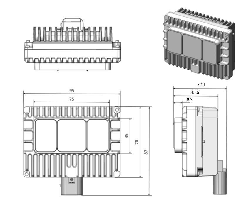
Figure 1 E1R shape and size diagram
2.2 Optical Envelope FOV Definition
The optical envelope of the E1R is shown in Figure 2. After all limits are accumulated, the optical envelope of the LiDAR cannot be blocked by exterior parts of the vehicle, such as LiDAR cover, roof panel, engine hood, and front bumper, which may block the field of view (FOV) of some parts. Figure 3 shows the FOV diagram of E1R.
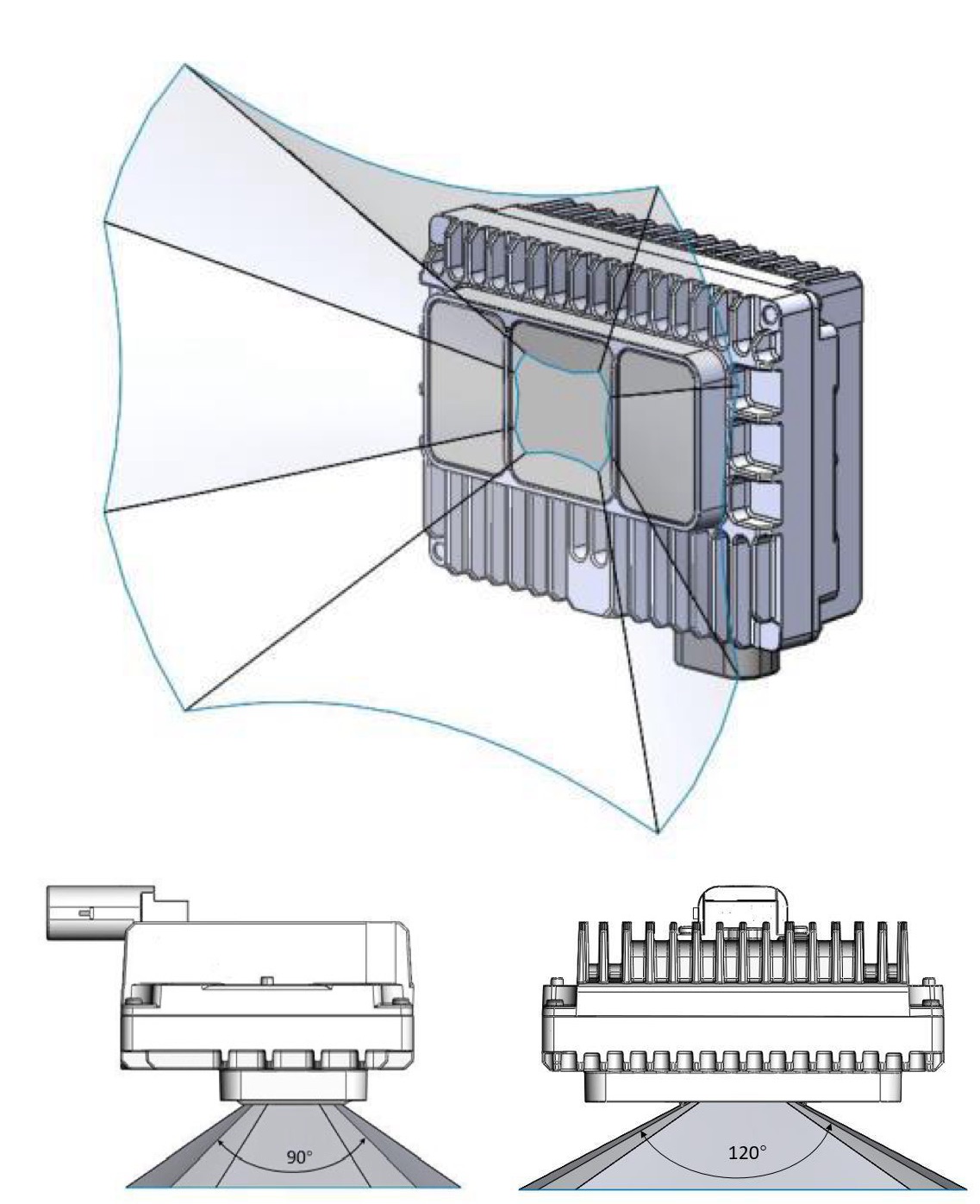
Figure 2 E1R FOV
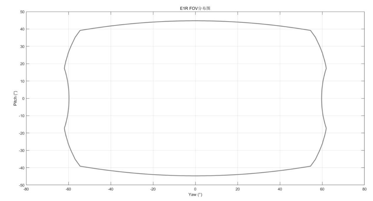
Figure 3 E1R FOV diagram
2.3 Product Specifications
The E1R uses a flash scanning method to measure distances up to 30 meters. Each frame produces a high number of points, at a rate of 26,000 points. The horizontal range of the scan is \(120^{\circ}\) (-60.0° to +60.0°), while the vertical range is \(90^{\circ}\) (-45° to +45°). For more details, please refer to Table 1.
Table 1 E1R Product Specifications
| E1R Product Specifications | ||||
|---|---|---|---|---|
| Ranging principle | Time of Flight | FOV(horizontal) | 120° (-60.0°~+60.0°) | |
| Wavelength | 940 nm | FOV(vertical) | 90° (-45°~+45°) | |
| Safety class | Class1 eye safe | Angular resolution(horizontal) | average 0.625°1 | |
| Ranging distance2 | 30m @10% NIS, 100klux direct sunlight | Angular resolution(vertical) | average 0.625°1 | |
| Blind area | 0.1 m | Ranging Precision3 | ±5cm@1 sigma | |
| Count of the points | ~260,000 points/second | Ethernet transmission rate | 1000Base-T1 Gigabit Ethernet | |
| Time Synchronization | gPTP (IEEE-802.1AS) PTP E2E L2 (IEEE-1588) |
Operating Voltage | 9V - 16V | |
| Frame rate | 10 Hz | Weight | 330 g±20g (only LiDAR) | |
| Power Consumption4 | <10W | Storage Temperature | -40°C ~ +105°C | |
| Operating Temperature5 | -40°C ~ +85°C | Protection Rating | IP67 / IP6K9K | |
| Size | Dimension | length (mm) | width (mm) | height (mm) |
| Size | Outer Contour | 95 | 42.6 | 69.5 |
| Size | Outer contour of main body with connector and installation position contour | 95 | 51.1 | 87 |
1 The vertical & horizontal angular resolution is not uniform in the entire FOV. The angular resolution is 0.625° in the center of the FOV and 0.7° at the edges of the FOV;
2 The ranging capability of 30 meters is measured with the 10% NIST diffuse reflector as the target, the test results may be affected by the environment conditions, including but not limited to factors such as ambient temperature and lights;
3 The ranging precision is tested in the range of 10m~30m with 50% NIST diffuse reflector as the target. The test results may be affected by the environment conditions, including but not limited to factors such as ambient temperature and target distance. The precision value is applicable to most channels, but difference may exist between some channels.
4 The test results of product power consumption will be affected by external environment, including but not limited to environmental temperature, distance of target object, reflection intensity of target object and other factors;
5 The operating temperature of the product may be affected by the external environment, including but not limited to the lighting environment, air flow changes and other factors;
2.4 Product Principle
2.4.1 Accurate Time Synchronization Protocol
The default firmware of E1R uses the gPTP (IEEE 802.1AS) time synchronization method.
2.4.1.1 Principle of gPTP synchronization
gPTP (general Precision Time Protocol) is a derived protocol from PTP (Precision Time Protocol) in Time-Sensitive Networking. The synchronization mechanism uses the same P2P end-delay mechanism as PTP, and it adopts communication at the Layer 2 of Ethernet. Unlike PTP, gPTP requires hardware timestamping, which imposes strict requirements on switches and master clocks (IEEE 802.1AS protocol is required).
2.4.1.2 gPTP wiring Method
To use the gPTP synchronization method, you need to make the following preparations, and then connect according to the connection method shown in the Figure 4.
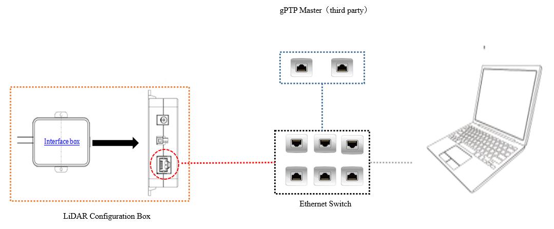
Figure 4 gPTP Connecting Diagram
- Prepare a gPTP Master timing host (plug and play, no additional configuration required);
- Ethernet switch;
- Device supporting gPTP protocol.
Note
- The Master timing equipment is a third-party equipment that needs to be purchased by the user independently, which is not included in the RoboSense standard product shipping package.
- RoboSense devices, as Slave devices, only obtain the time from the Master and do not judge the accuracy of the Master clock source. If there are sudden changes in the time resolution of the LiDAR point cloud, please check if the provided time by the Master is accurate.
- After the LiDAR is synchronized, the Master is disconnected, and the time in the point cloud data packet will be superimposed according to the LiDAR's internal clock, and it will be reset after the LiDAR is powered off and restarted.
2.4.2 Use Linuxptp tool to verify time synchronization
Connect the E1R power cable and network cable to the Interface Box, and then connect the other end of the network cable to the upper computer. The operating system (OS) of the upper computer must be a Linux system, and here we take Ubuntu as an example.
-
Use the command $ifconfig to check the network card name. As shown in the figure, the network card name is enp2s0.
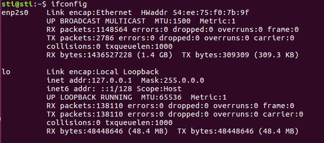
Figure 5 Illustration of Finding Network Card Name
-
Use the command $ ethtool -T enp2s0 (the network card name obtained in the previous step), you can check if this card supports PTP hardware. For gPTP synchronization, hardware support is required, and the PTP Hardware Clock option requires a value other than none.
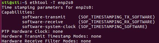
Figure 6 Illustration of checking PTP hardware support
-
Download and install the linuxptp tool.
sudo git clone git://git.code.sf.net/p/linuxptp/code linuxptp cd linuxptp sudo make sudo make install reboot -
The use of the ptp4l command.
Here are some options for using the ptp4l command:
-
Delay mechanism options
- -A Automatic mode, automatically selects the E2E delay mechanism when receiving a peer delay request and switches to P2P mode.
- -E E2E mode, request-response delay mechanism (default)
- -P P2P mode, end-to-end delay mechanism
-
Network transport options
- -2 IEEE 802.3
- -4 UDP IPV4 (default)
- -6 UDP IPV6
-
Timestamp options
- -H Hardware timestamp (default)
- -S Software simulation timestamp
- -L The old hardware timestamp, and LEGACY_HW requires cooperation with PHC devices.
-
Other options
- -f [file] Read configuration from the specified file. By default, no configuration file is read.
- -i [dev] Select the PTP interface device, such as eth0 (can be specified multiple times). The dev parameter must be used with this option or a port is specified in the configuration file.
- -p [dev] This option is used to specify the PHC device to be used on older Linux kernels (such as /dev/ptp0 clock device), the default is auto, ignoring both software/ LEGACY_HW time stamps (not recommended to use this option)
- -s SlaveOnly mode, overrides the clock mode from the configuration file
- -t Transparent clock mode
- -1 [num] Set the logging level to 'num', the default is 6
- -m Print messages to stdout
- -q Don't print messages to syslog
- -v Print software version and exit
- -h Help command
Additionally, here are some simple commands for synchronizing E1R using the PTP protocol:
-
PTP E2E (L2 layer) command:
sudo ptp4l -E -S -2 -m -i enp2s0(the name of the network card)The device requires hardware support for PTP Hardware Clock, and it is not a "none" value. In this case, you can use "-H" instead of "-S".
-
The gPTP command:
sudo ptp4l -i enp4s0 -m -H -2 -f gptp-master.cfgThe device requires hardware support for PTP Hardware Clock, which is not a "none" value. In this case, gptp-master.cfg is the gPTP master clock configuration file.
Create a new gptp-master.cfg file on the host, and copy the following content into this file, then save the file:
# 802.1AS example configuration containing those attributes which
# differ from the defaults. See the file, default.cfg, for the
# complete list of available options.
[global]
domainNumber 0
logSyncInterval -3
syncReceiptTimeout 3
neighborPropDelayThresh 800
path_trace_enabled 1
follow_up_info 1
transportSpecific 0x1
ptp_dst_mac 01:80:C2:00:00:0E
#p2p_dst_mac 01:1B:19:00:00:00
network_transport L2
delay_mechanism P2P
masterOnly 1
BMCA noop
asCapable true
inhibit_announce 1
inhibit_delay_req 1
Note
For devices without hardware support, you can use -S instead of -H for gPTP synchronization simulation. However, the synchronization accuracy cannot be guaranteed.
2.4.3 GPS Time Synchronization
If you need to synchronize the E1R with a GPS module, first you need to enable the GPS module to provide time synchronization to the gPTP Master. The specific interface and synchronization method needs to be clear with the gPTP master provider. Unless there are special requirements, RoboSense will not provide related technical support.
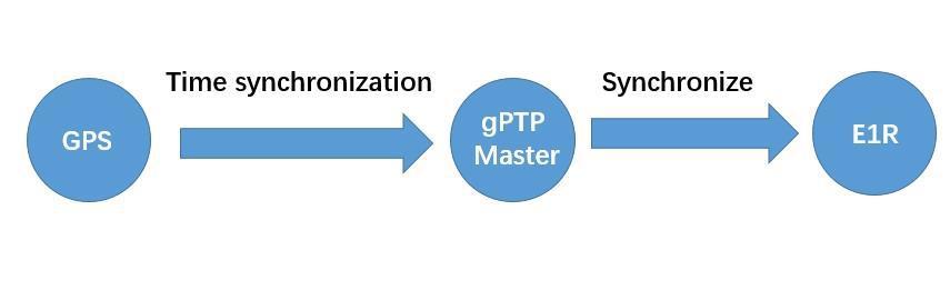
Figure 7 Topology Diagram of GPS Synchronization
3 Product Installation Recommendations
3.1 Interface Description
3.1.1 E1R Platform Connector
The TE 2397179-1 connector scheme is recommended for the E1R platform, custom connector models are not accepted, and the bending radius of the wiring harness is greater than 30 mm, and the specific connector scheme can be seen in Table 2.
Table 2 Connector Scheme
| Connector Scheme | Connection Type | Model | Picture | Function |
|---|---|---|---|---|
| TE Bow-mount Type (Two-in-one plug, 6+2pin) | LiDAR End Connector | TE 2397179-1 | 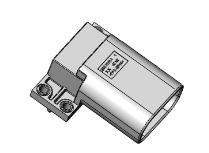 |
Power + Gigabit Ethernet |
| Wire harness connector | TE 2397144-1 | 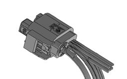 |
Power + Gigabit Ethernet |
3.1.2 Connection Installation Requirements
- The waterproof ring of the wire harness end connector should be well-compatible with the wire material and meet IP67 and IP6K9K waterproof levels;
- The outgoing cable location of the wire harness end connector at the end should have a hand-preserved space of at least 70mm around the environment.
3.1.3 Whole Car Wire Harness End Installation Requirements
- The material of the Ethernet wire harness should use STP wires that meet 1000BASE-T1;
- It is recommended to use Dacra 686-3 (bending radius 25mm) or GG X9305 (bending radius 12mm) for the whole car wire harness;
- The total length of the Ethernet wire harness is recommended to be less than 15m, However, considering the loss at the board end, it is recommended that the wiring harness in practical applications does not exceed 12 meters, and the number of connectors should not exceed 3 pairs (including wire pairs);
- Ethernet signal lines should be routed in the entire car, and it is recommended to avoid moving sections and high-temperature areas;
- Power supply needs to consider cable length, wire diameter, and impedance, and the LiDAR working voltage on the power line should remain above 9V-16V;
- It is recommended that the LiDAR harnesses exposed to the outside be designed with waterproof rubber sleeves.
3.2 The Connection of Interface Box
3.2.1 Vehicle Ethernet Harness Interface and Definition
E1R uses a car Ethernet and power 2-in-1 connector, and the wiring harness is shown in Figure 8.
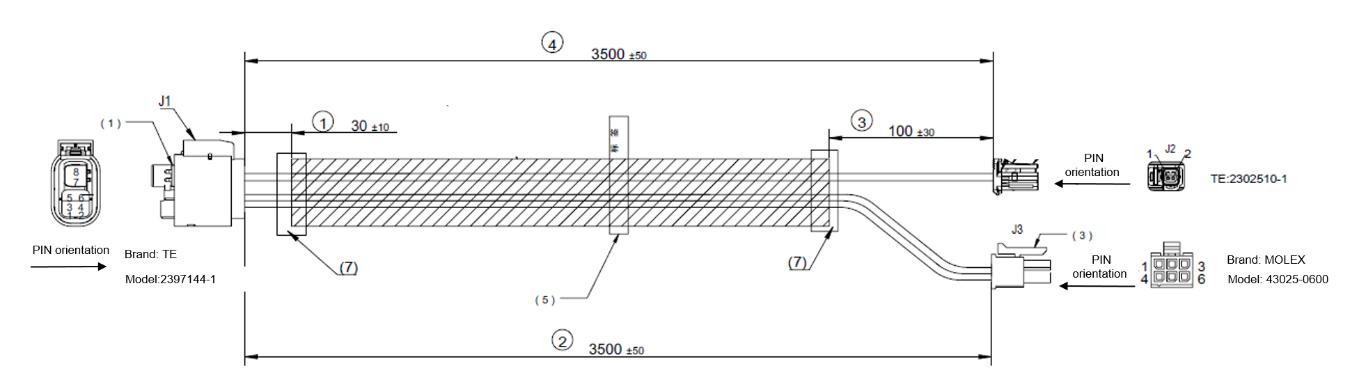
Figure 8 Direct Connection between LiDAR Equipment and Host Computer
3.2.2 Interface Box
The connection description of E1R interface box is shown in Table 3:
Table 3 Wiring Description
| Wiring Description | TE Interface Box Structure Diagram |
|---|---|
| Connecting to the LiDAR side | 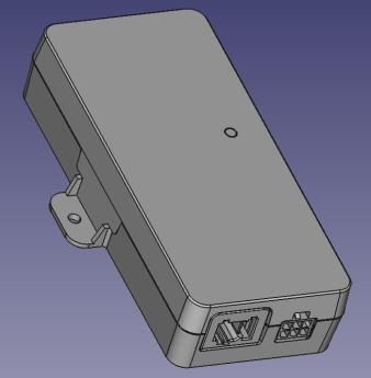 |
| Connecting to the power supply and host computer side | 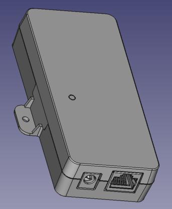 |
3.2.3 Power Interface
E1R interface box uses standard DC 5.5-2.1 interfaces.
When the power supply is normal, the green indicator of the power supply box is steady on. When the green indicator is off, check whether the power input is normal. If the power input is normal, the interface box may be damaged. Contact RoboSense.
3.2.4 RJ45 network port
The E1R body supports only 1000BASE-T1 on-board Ethernet. When the interface box is used, the network interface uses the standard RJ45 interface. The interface box supports only Gigabit Ethernet.
3.3 LiDAR State Machine
Refer to Figure 9 for the description of the LiDAR state machine. When the wake-up pin inputs a high level of 9-16V, the LiDAR wakes up.
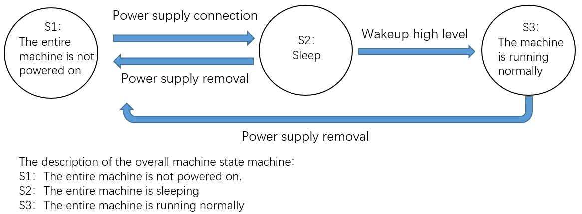
Figure 9 LiDAR State Machine Description
3.4 Installation and positioning methods recommendation
3.4.1 Installation tolerance requirements
Considering the cumulative error of the entire machine, it is recommended that the installation tolerance requirements for the LiDAR:
- The installation position accuracy in the X, Y and Z directions is \(\pm3mm\) ;
- The installation Angle accuracy in the Roll, Yaw and Pitch directions is \(\pm1.5^{\circ}\)
The final requirements are subject to the actual installation needs
3.4.2 Installation bracket positioning and fastening requirements
As shown in Figure 10, it is recommended to position the LiDAR upright. It is not advisable to position the LiDAR upside down or for measurement
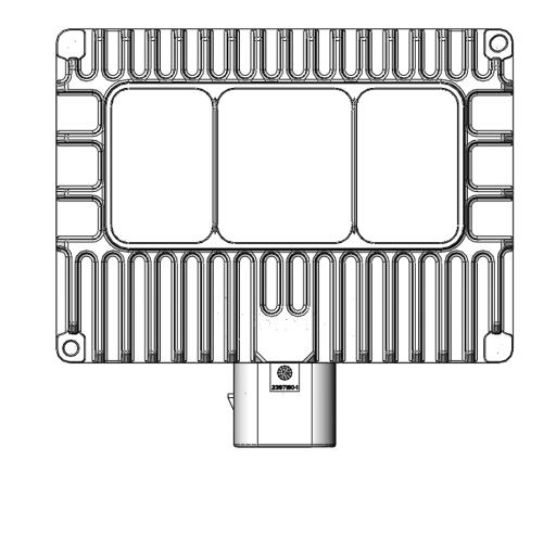
Figure 10 LiDAR installation direction indication (upright)
3.4.3 Installation bracket position
The rear shell of the LiDAR is equipped with 4 M4 screw holes or vias, as well as 2 positioning columns, as shown in Figure 11. The rear shell positioning column and the bracket positioning hole are in coordination. The bracket is set with 4 fixed holes, which are connected to the 4 threaded holes of the rear shell by threads to complete the installation of the LiDAR.
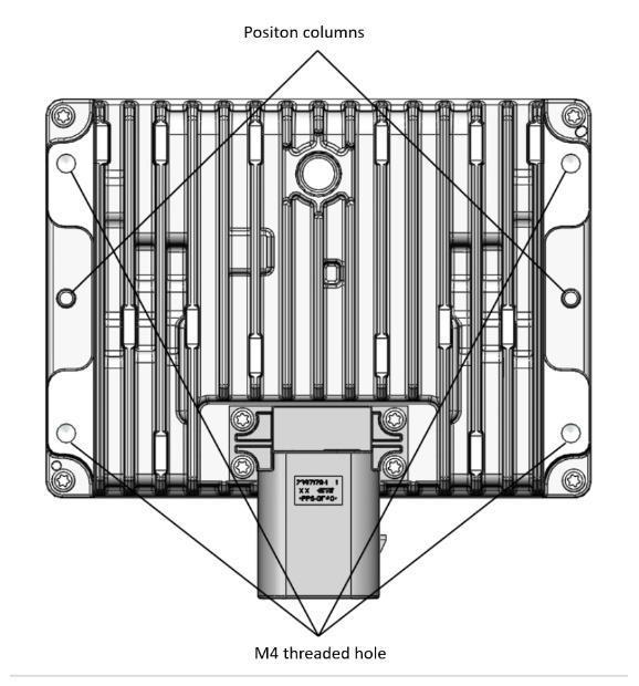
Figure 11 Fix position for install bracket
3.4.4 Requirements for positioning and fastening of the installation bracket
- It is recommended to use the positioning method of the rear wing panel positioning hole/positioning column
- It is recommended to use small protrusions near the four installation holes for the LiDAR bracket to cooperate with the LiDAR. The overall flatness of the protrusions should be within 0.5mm
- The pitch of the M4 screw hole is 0.7mm;
- The recommended strength grade of the M4 screw at the bottom is 8.8 or above;
- The recommended torque is \(2.7 \pm 10\%\) N·m, subject to the calibration result of the screw;
- It is recommended that the screw length be T + 3mm of the bracket thickness, and the effective number of engaged teeth be 4 or more;
3.5 Design and requirements for installation bracket
The fixed bracket needs to have good rigidity for installing and fixing the LiDAR, and to keep the LiDAR in a stable state under various working conditions. The design requirements are as follows:
- The LiDAR installation scenarios involve various load environments such as vibration and shock. The LiDAR bracket should have a certain degree of rigidity to ensure the stable operation of the LiDAR under different load environments. It is recommended that the LiDAR bracket maintains a certain rigidity. The specific boundary requirements are determined by the customer's perception algorithm. This recommendation stems from the fact that perception algorithms typically aim to keep the relative position relationship between the LiDAR and the fixed part as well as other sensors as fixed as possible under external vibration excitation, rather than considering the reliability of LiDAR usage. Different perception algorithms have different requirements for the relative position relationship between sensors, which should be evaluated and confirmed by the customer;
- After experiencing random vibration, mechanical shock and other working conditions, the radar support will bear a relatively large load. The strength of the support should be checked in combination with the actual working conditions. Under mechanical shock conditions, the maximum stress of the fixed parts should be less than two-thirds of the tensile strength. Under random vibration conditions, the 1sigma RMS stress of the fixed part should be less than 1/5 of the tensile strength;
3.6 Cooling requirements for installation brackets
-
Cooling requirements: During the use of E1R, there will be some heat, and the radiation from the body's own heat source may aggravate the temperature rise of E1R, and the heat dissipation requirements are as follows:
- The installation bracket for E1R should be an excellent heat transfer material and should avoid being enclosed in the bracket as much as possible;
- The front and rear ends of E1R are the main heat dissipation surfaces;
- The bracket is recommended to use aluminum alloy with a thermal conductivity coefficient of more than 50 W/m·K or galvanized steel plate, etc.;
- Some cooling fins should be added to the bracket and the fin spacing/height/direction should be controlled reasonably to increase the cooling area as much as possible, consistent with the air flow direction;
- It is recommended to provide the installation bracket model and installation environment information to Robosense for thermal simulation confirmation.
-
Working temperature requirements.
- There should be a gap between E1R and surrounding components (greater than 5mm), and the installation parts should not completely enclose the LiDAR, but rather open some holes to ensure better air flow;
- In principle, as long as the ambient temperature around E1R does not exceed \(85^{\circ}\) C under any conditions, it can meet the working temperature requirements.
3.7 Recommended solution for E1R Lidar cover
The opening size of the LiDAR cover is determined by factors such as the FOV deviation after LiDAR calibration and installation errors. The specific structure is determined according to the customer's requirements.
- The FOV envelope area of the LiDAR is strictly prohibited from any obstructions (including transparent glass materials), as obstructions will affect the ranging capability of the LiDAR;
- The edge of the LiDAR cover sheet is prone to damage or fragmentation when impacted by external sharp objects such as crushed stones. If the window edge protrudes beyond the LiDAR housing, there is a risk of failing the stone impact test.
Any design featuring a protruding window edge must undergo prior assessment of stone impact test risks.
4 LiDAR Usage
4.1 Coordinate System
The coordinate system definition of E1R is shown in Figure 12.
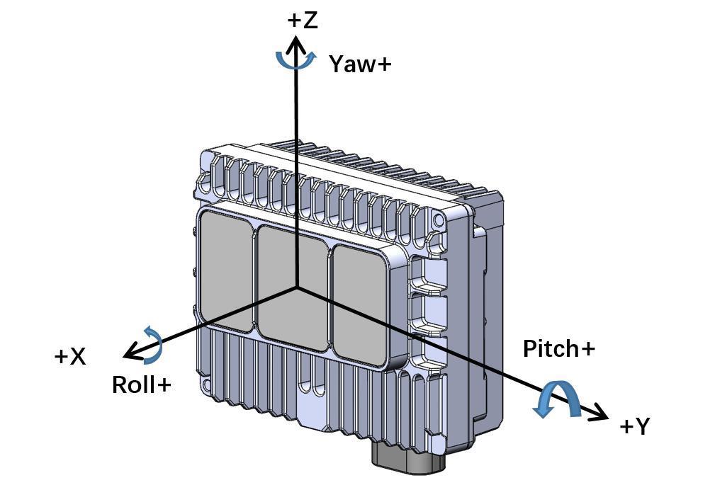
Figure 12 E1R Coordinate System Definition
4.2 RSView
In the detection of data from E1R, free tools such as Wireshark and tcp-dump can be used to obtain raw data. Meanwhile, RSView can assist users in visualizing raw data more conveniently.
4.2.1 Software Features
RSView provides real-time visualization of any RoboSense LiDAR data. RSView can also review pre-recorded data stored in “pcap” (Packet Capture) files, but RSView still does not support playing “.pcapng” files.
RSView displays distance measurements from a RoboSense LiDAR as point data. It supports custom-colored display of variables such as intensity-of-return, time, distance, azimuth, and laser ID. The data can be exported in CSV format. The RSView 4.3.11 or later version supports generating LAS format point cloud files.
Functionality and features of RSView include:
- Visualize live streaming sensor data over Ethernet
- Record live sensor data to pcap files
- Visualize sensor data from a recorded pcap file
- Different types of visualization modes, such as distance, time, azimuth, etc.
- Display point data in a spreadsheet
- Export point cloud data in CSV format
- Distance measurement tool
- Display multiple frames of data simultaneously (Trailing Frames)
- Crop views
4.2.2 Install RSView
RSView supports running on Windows 64-bit, Ubuntu 18.04 or higher operating systems. You can download the latest installer from RoboSense website (https://www.robosense.ai/en/resources). Launch the downloaded installer and follow the instructions to finish the installation. After installation is completed, a shortcut will be generated on the desktop. Make sure the installation path only contains English characters.
4.2.3 Use RSView
For details on using RSView for operation, please refer to the RS-LiDAR User Guide by pressing the F1 button, or clicking the Help option in menu bar.
4.3 Communication Protocol
The communication between E1R and the computer is through Ethernet, and uses UDP protocol. There are two types of output packets: MSOP packet and DIFOP packet.
All MSOP packets involved in this document are with fixed length of 1200 bytes, DIFOP packets are with fixed length of 256 bytes. E1R network parameters are configurable, and the factory default IP and fixed client port number are set as listed in the Table 4:
Table 4 Factory default network configuration
| IP Address | MSOP Port Number | DIFOP Port Number | |
|---|---|---|---|
| E1R | 192.168.1.200 | 6699 | 7788 |
| Computer | 192.168.1.102 | 6699 | 7788 |
The default MAC address of the LiDAR is initially set at the factory, and the MAC address of each LiDAR is unique.
When using the LiDAR in unicast mode, you need to set the computer's IP to the same network segment as the LiDAR, for example, 192.168.1.x (the range of x is 1~254), and the subnet mask as 255.255.0.0. If you don't know the network configuration information of the LiDAR, please set the host computer subnet mask to 255.255.0.0 to connect to the LiDAR and use Wireshark to capture the LiDAR output packet for analysis.
The communication protocol between E1R and the computer is mainly divided into two categories. See the Table 5 for the protocol list.
The main data stream output protocol (MSOP), encapsulates the distance, angle, reflectivity and other information measured by the LiDAR into a package and outputs it to the computer.
LiDAR information output protocol (DIFOP), outputs various configuration information of the LiDAR currently in use to the computer.
Table 5 List of communication protocols
| Protocol | Abbreviation | Function | Type | Packet size |
|---|---|---|---|---|
| Main Data Stream Output Protocol | MSOP | Output measured data | UDP | 1200 Bytes |
| Device Information Output Protocol | DIFOP | Output device information | UDP | 256 Bytes |
4.3.1 Main Data Stream Output Protocol (MSOP)
Main data Stream Output Protocol is abbreviated as MSOP.
I/O type: LiDAR output, computer analysis.
Default port number: 6699.
The MSOP packets output three-dimensional measurement related data, including laser ranging value, return reflectivity value, vertical angle, horizontal angle and time stamp. The payload length of the MSOP packet is 1200 bytes, which consists of a synchronization header of 32 bytes, a data packet of 1152 bytes (a total of 96 data blocks of 12 bytes), and a tail of 16 bytes.
The basic structure of the MSOP packet is as shown in the figure below:
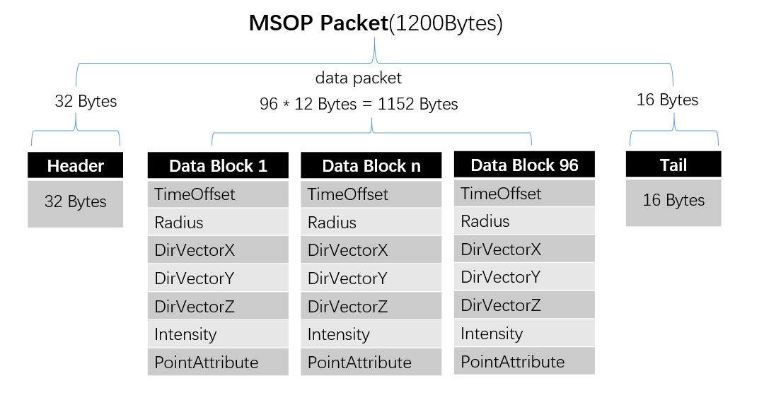
Figure 13 MSOP Packet Structure
4.3.1.1 Header
The header is 32-bytes long, and is used for identification of the starting position of data, packet counting, UDP communication reservation, and time stamp storage. The detailed definition is as follows:
Table 6 MSOP Header
| Header(32Bytes) | ||||
|---|---|---|---|---|
| Sync | PktCnt | Ver | ReturnMode | TimeMode |
| 4 Bytes | 2 Bytes | 2 Bytes | 1 Byte | 1 Byte |
| Timestamp | FrameSync | Res0 | LidarType | LidarTmp |
| 10 Bytes | 1 Byte | 9 Bytes | 1 Byte | 1 Byte |
Sync: can be used as a packet inspection sequence, and the identification header is 0x55, 0xaa, 0x5a, 0xa5.
PktCnt: Packets Sequence Number, packet counting in a circular counting manner, the count value of the first data packet of each frame is 0, the count value of the last data packet of each frame is the maximum value.
Ver: version number of the UDP communication protocol.
ReturnMode: return mode flag, 4 means strongest return, which is fixed.
TimeMode: time synchronization mode: - 0x00: currently using the LiDAR internal timing. - 0x02: currently using PTP E2E time synchronization mode. - 0x03: currently using gPTP time synchronization mode.
Timestamp: store timestamps. The defined timestamp is used to record the system. time. The high 6 bytes are the second bits, and the low 4 bytes are the microsecond bits.
FrameSync: frame synchronization state (0x00:no 0x01:yes)
Res0: reserved bit
LidarType: the type of LiDAR, default is 0x62.
LidarTmp: LiDAR's temperature, Temp = LidarTmp - 80
4.3.1.2 Data Packet
The data packet in the MSOP packet stores the data measured by the LiDAR, it has a total of 1152 bytes consisting of 96 data blocks, each data block has 12 bytes.
The detailed definition is as follows:
Table 7 Definition of data block in MSOP packet
| Data block (12Bytes) | |||
|---|---|---|---|
| content | offset | byte | instruction |
| TimeOffset | 0 | 2 | The time offset of all points in the block relative to the timestamp of the packet, the time of this group of points equals to Timestamp + time_offset |
| Radius | 2 | 2 | In the polar coordinate system, the radial distance value of the points, the distance resolution is 5mm |
| DirVectorX | 4 | 2 | Unit direction vector X axis component of channel 1, the value ranges from -32768 to 32767, and divides by 2^15 to float. |
| DirVectorY | 6 | 2 | Unit direction vector Y axis component of channel 1, the value ranges from -32768 to 32767, and divides by 2^15 to float. |
| DirVectorZ | 8 | 2 | Unit direction vector Z axis component of channel 1, the value ranges from -32768 to 32767, and divides by 2^15 to float. |
| Intensity | 10 | 1 | Reflection intensity value of the channel 1 points, the value range is 0~255 |
| PointAttribute | 11 | 1 | Attribute of the channel 1 point, 1 indicates normal, 2 indicates noisy point |
Related calculation specification
Calculation of the radial distance:
(Radius is 2-byte long, the unit is millimeter, and the resolution is 5mm.)
Get the hexadecimal number of the radius value of a charnel in the data packet:
R1 is 0x03, R2 is 0xfc
0x03 is the high digit of the distance, converted to decimal is 3, 0xfc is the low digit of the distance, converted into decimal is 252.
Therefore: the radial distance of this channel=R1256+R2=3256+252=1020.
According to the resolution of the coordinates, it is converted to meters: 1020 *0.005=5.10m.
Therefore, the radial distance of this channel in the corresponding elevation and azimuth direction is 5.1 m.
Calculation of XYZ coordinates:
XYZ coordinates can be calculated from the following equations:
4.3.1.3 Tail
The frame tail contains parameters used by LiDAR E2E Profile4, The detailed definition is as follows:
Table 8 Definition of tail in MSOP packet
| content | offset | byte | instruction |
|---|---|---|---|
| Res1 | 1184 | 4 | Reserved |
| DataLength | 1188 | 2 | 04 B0 |
| Counter | 1190 | 2 | 00 00~FF FF |
| DataId | 1192 | 4 | 00 00 0E 5D |
| Crc32 | 1196 | 4 |
4.3.2 LiDAR Information Output Protocol (DIFOP)
LiDAR Information Output Protocol is abbreviated as DIFOP
I/O type: LiDAR output, computer read.
Default port number: 7788.
DIFOP is an "output-only" protocol to periodically send the LiDAR serial number (S/N), firmware version information, host computer driver compatibility information, network configuration information, calibration information, operating status, and fault diagnosis information to users. By reading DIFOP, users can learn specific information of various parameters of the LiDAR currently in use.
The detailed definition is as follows:
Table 9 Definition of DIFOP packet
| DIFOP Packet(256Bytes) | |||
|---|---|---|---|
| content | offset | byte | instruction |
| DifopHeader | 0 | 8 | DIFOP recognition head |
| Res0 | 8 | 8 | Reserved |
| SW Version | 16 | 3 | LiDAR SW version information |
| Res1 | 19 | 1 | Reserved |
| SN | 20 | 6 | Serial number |
| Res2 | 26 | 18 | Reserved |
| LocalIp | 44 | 4 | LIDAR IP Source address |
| NetMask | 48 | 4 | Subnet mask |
| MacAddress | 52 | 6 | LIDAR IP Local MAC address |
| MsopRemoteIp | 58 | 4 | Msop Remote IP |
| MsopLocalPort | 62 | 2 | Msop Local Port |
| MsopRemotePort | 64 | 2 | Msop Remote Port |
| DifopRemoteIp | 66 | 4 | Difop Remote IP |
| DifopLocalPort | 70 | 2 | Difop Local Port |
| DifopRemotePort | 72 | 2 | Difop Remote Port |
| Res3 | 74 | 25 | Reserved |
| FrequencySetting | 99 | 1 | LiDAR frame rate setting |
| ReturnMode | 100 | 1 |
LiDAR echo information: 0x00: FarthestWave 0x04: StrongestWave (Default) 0x07: NearestWave 0x08: 2ndStrongestWave 0x09: StrongestFarthestWave 0x0A: NearestFarthestWave 0x0B: Strongest2ndStrongestWave |
| TimesyncMode | 101 | 1 |
Time synchronization mode: 0x0: Internal 0x2: E2E L2 0x3: gPTP |
| TimesyncStatus | 102 | 1 |
Time synchronization status: 0x00: failed 0x01: success 0x02: timeout |
| TimeStatus | 103 | 10 |
Timestamp: 0-5bytes: Second 6-9bytes: MicroSecond |
| PHYMode | 113 | 1 |
PHY Mode: 0x00: auto-negotiation 0x01: Master 0x02: Slave Other: same as 0x00 |
| Res4 | 114 | 142 | Reserved |
6 Product Maintenance
6.1 Transportation and Logistics
Improper transportation can cause product damage
- The product should be packaged with shockproof and moisture-proof materials to avoid damage during transportation. It is recommended to use the original packaging;
- Handle with care during transportation to avoid impact or dropping;
- When receiving the goods, carefully check the delivery list for any damages (including the product and packaging);
- If there is any transportation damage, refuse to accept the delivery and contact RoboSense promptly.
6.2 Storage
Improper storage may cause product damage
- Store the product in an indoor environment with normal temperature and dry conditions;
- Handle the product gently to avoid impact or dropping;
- The product should be stored in a safe environment to avoid corrosion, mechanical impact, or exposure to environments exceeding the protection level;
- Regularly inspect the condition of all components and packaging, and it is recommended to check every three months.
6.3 Product Cleaning
To ensure accurate perception of the surrounding environment, keep the RS-LiDAR's circular protective cover clean.
6.3.1 Precautions
Note
- Before cleaning the RS-LiDAR, carefully read and understand the content of this section. Improper cleaning may damage the product.
- When using the LiDAR in harsh environmental conditions, clean the surface regularly to keep the LiDAR clean. Otherwise, it may affect the normal operation of the LiDAR.
6.3.2 Required Materials
- Clean and dust-free cloth;
- Neutral solution at moderate temperature (such as soapy water, distilled water, 99% concentration of ethanol, etc.).
6.3.3 Cleaning Method
-
If the LiDAR surface is only covered with some dust:
- Use a clean and dust-free cloth, dip it in a small amount of neutral solution;
- Gently wipe the LiDAR surface;
- Dry it with a clean and dry dust-free cloth.
-
If the LiDAR surface is covered with mud or other solid foreign objects:
- First, spray clean water on the dirty part of the LiDAR surface to remove the mud or foreign objects (Note: Do not directly wipe off the mud with a dust-free cloth, as it may scratch the surface, especially the protective cover);
- Then spray warm soapy water on the dirty part. The lubricating effect of the soapy water helps to remove the foreign objects. Gently wipe the LiDAR surface with a fiber cloth, but be careful not to scratch the surface;
- Finally, rinse off the residual soap on the LiDAR surface with clean water (if there is still residue, clean it again with 99% ethanol) and dry it with a clean and dry dust-free cloth.
7 After-sale service
If the solutions provided in Chapter 6 of the troubleshooting guide do not solve the problem, please promptly contact RoboSense.
Official Website: https://www.robosense.cn/en/contact
Email: support@robosense.cn
Phone: +86-0755-86325830 / +86-15338772453
Info
- Please wait for a confirmation response from RoboSense after-sales service before sending the product back;
- When sending the product back, please use the original packaging or an equivalent cushioned and moisture-resistant packaging.
Appendix A Driver & SDK
A.1 Compile and Install rs_driver
RS Driver provides a cross-platform LiDAR driver kernel for RoboSense LiDAR products, which is convenient for users to re-develop and use. The driver kernel of v1.5.10 and later versions already support analysis and transformation of E1 point cloud. Users can download the rs_driver package from our official account on GitHub :
https://github.com/RoboSense-LiDAR/rs_driver
rs_driver currently supports the following systems and compilers:
-
Windows:
- MSVC (VS2017 & VS2019 tested)
- Mingw-w64 (x86_64-8.1.0-posix-seh-rt_v6-rev0 tested)
-
Ubuntu (16.04, 18.04, 20.04):
- gcc (4.8+)
A.1.1 Install Dependent Libraries
rs_driver depends on the following third-party libraries, which need to be installed before compilation:
- Boost
- Pcap
- PCL (not required, can be ignored if visualization tools are not needed)
- Eigen3 (not required, can be ignored if built-in coordinate transformation is not needed)
Install the above dependent libraries in Ubuntu:
sudo apt-get install libboost-dev libpcap-dev libpcl-dev libeigen3-dev
Install the above dependent libraries in Windows:
-
Boost
The Boost library needs to be compiled from source code under Windows, please refer to the official guide. After compiling and installing, add the path of Boost to the system environment variable
BOOST_ROOT.If you use MSVC, you can also choose to directly download the pre-compiled installation package of the corresponding version.
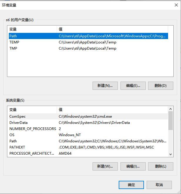
Add environment variables
-
pcap
First, install the pcap runtime library. Download the developer package to any location. Then, add the path of
WpdPack_4_1_2/WpdPackto the environment variablePATH. -
PCL (not required, can be ignored if visualization tools are not needed)
-
MSVC
If you are going to use the MSVC compiler, please install the official installation package provided by PCL. Select "Add PCL to the system PATH for xxx" during installation:
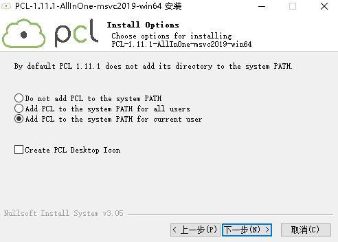
PCL Set up
-
Mingw-w64
PCL does not provide the official mingw compilation library, users need to compile PCL from source code and install it according to the official tutorial.
-
A.1.2 Use of rs_Driver
A.1.2.1 rs Driver Installation and Use
Take the Linux environment as an example for driver compilation (rs_driver currently does not support installation and use in windows system), execute the following codes to install the driver
cd rs_driver
mkdir build && cd build
cmake .. && make -j4
sudo make install
A.1.2.2 Use as a Submodule
When rs_driver is used as a submodule, the following commands need to be added to the CMakeLists.txt file. (add rs_driver as a submodule to the project, use the find_package() instruction to find rs_driver, and then link the relevant library).
add_subdirectory( $PROJECT_SOURCE_DIR$ /rs_driver)
find_package(rs_driver REQUIRED)
include_directories( $rs_driver_INCLUDE_DIRS$ )
target_link_libraries(project $rs_driver_LIBRARIES$ )
A.1.3 Demo Programs & Visualization Tools
A.1.3.1 Demo Programs
rs_driver provides two demo programs. Users can refer to the demo programs to write code, call interfaces and store them in rs_driver/demo:
- demo_online.cpp
- demo_pcap.cpp
To compile the two demo programs, users can add the parameters when executing the CMake configuration.
cmake -DCOMPILE_DEMOS=ON ..
A.1.3.2 Visualization Tools
rs_driver provides a point cloud visualization tool based on PCL, which is stored in rs_driver/tool:
- rs_driver_viewer.cpp
To compile the two demo programs, users can add the parameters when executing the CMake configuration:
cmake -DCOMPILE_TOOLS=ON ..
A.1.4 Coordinate Transformation
rs_driver provides a built-in coordinate transformation feature, which can directly output the point cloud after coordinate transformation, which saves users the time-consuming extra operations of coordinate transformation on the point cloud. If you want to enable this feature, add the parameters when executing CMake configuration:
cmake -DENABLE_TRANSFORM=ON ..
A.2 Compile and Install rslidar_sdk
rslidar _sdk is the ROS-based driver SDK. You can download it from the RoboSense GitHub repository or contact RoboSense for access.
-
rslidar_sdk depends on rs_driver, which is the basic RoboSense driver.
-
If you are using ROS2, rslidar_sdk also depends on rslidar_msg, which defines the message format.
-
The SDK package contains comprehensive usage guidelines. Before using the driver SDK, please read the README file and documentation under the doc folder.
Appendix B Mechanical Drawings
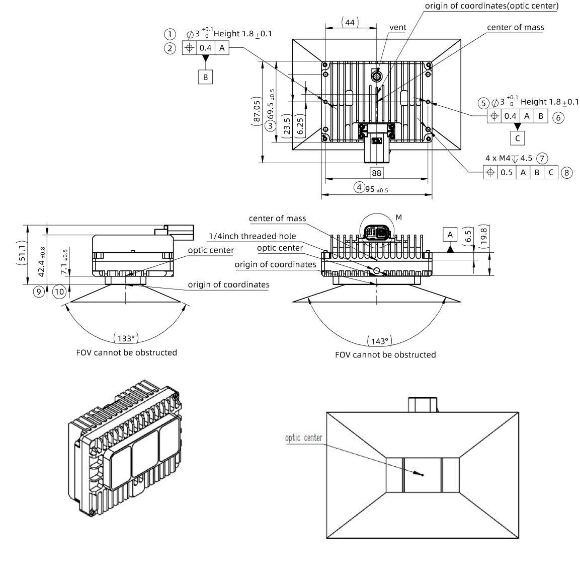
Drawing of LiDAR with TE Connector
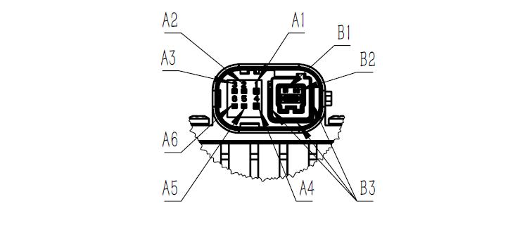
Definition of TE-Pins
Table 10 Pin definitions for connectors
| Pin number | number | Pin definition | Connector model |
|---|---|---|---|
| A1 | 1 | Battery+ | TE-2397179-1 |
| A2 | 2 | Wakeup(KL15) | |
| A3 | 3 | NC | |
| A4 | 4 | GND | |
| A5 | 5 | NC | |
| A6 | 6 | NC | |
| B1 | D1 | TRX_P(1000Base-T1) | |
| B2 | D2 | TRX_N(1000Base-T1) | |
| B3 | / | SHIELD |