EMX
1 Safety Notices
1.1 Legal Statement
Warning
Unless otherwise stated, all rights (including copyrights, trademarks, patents, trade secrets, and other related rights) in RoboSense's products, technologies, software, programs, data, and other information (including text, icons, photographs, audio, video, graphics, color combinations, layout design, etc.) are owned by RoboSense and its licensors.
No one may use any content contained in this manual in any unauthorized manner without the prior written consent of RoboSense.
The word "RoboSense" and other logos and product and service names are owned by RoboSense. If you need to use them for any advertising or displaying purposes, you must obtain prior written authorization from RoboSense.
1.2 User Guidelines
Please use this product in accordance with the following requirements
- Please strictly abide by relevant national laser safety laws and regulations;
- Please read this product manual in detail before using the product;
- Please use this product only in the relevant field of application;
- Please avoid using this product in environments that are explosive, highly corrosive, or beyond the IP protection level of the equipment.
1.3 Illegal Operation
Please use this product in accordance with the regulations, otherwise it may cause product damage, property loss, and personal injury. Users are responsible for risk arising from unauthorized operations.
- Do not disassemble or modify this product (including accompanying accessories);
- Non-specified power supply and accompanying accessories are prohibited;
- Please avoid abnormal operations such as dropping, colliding, burning, etc.;
- If you notice any damage to the appearance of the device (arc protection cover), please immediately stop using it;
- If you notice any abnormal operation of the product, please immediately stop using it and contact RoboSense in a timely manner.
1.4 Requirements for Operating Personnel
The use of this product requires certain basic professional knowledge and other related requirements for operating personnel. Unreasonable operations performed by personnel without basic knowledge or training do not constitute a fault of RoboSense and may cause damage to equipment and personal property.
- Please read the product manual in detail before using the device;
- Prohibit illegal operations;
- Before working, personnel must undergo training and obtain relevant construction qualifications;
- Have some basic knowledge of computer data connection, electrical, and so on.
1.5 Work Safety and Special Hazards
To avoid risks of accidents, damage to sensor or violating of your product warranty, please read and follow the instructions in this manual carefully before operating the product.
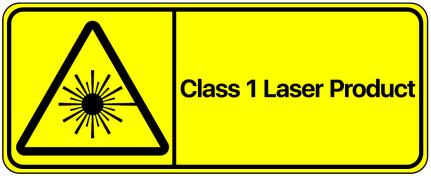
- Laser Safety: This product meets the following standards for laser products: IEC 60825-1:2014;
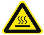
- High Temperature Warning: Please pay attention to the overheating sign on the LiDAR surface to avoid a hot LiDAR surface that may lead to sensor failure or undesirable consequences;
-
Retain Instructions: The safety and operating instructions should be retained for future reference;
-
Heed Warnings: All warnings on the product and in the operating instructions should be adhered to;
-
Servicing: Except for what's described in this manual, the sensor has no field serviceable parts. For servicing, please contact RoboSense sales or the authorized distributors.
2 Product Description
The following content describes the status and functionality of the EMX B0 sample. The product manual will be updated to the latest version when new versions of the sample are released.
2.1 Product Overview
EMX is a new generation of RoboSense 192-line automotive-grade high-performance digital LiDAR, providing high-definition point clouds with 192 lines and 2.88 million points per second, with a global angular resolution of 0.1*0.1°, and a maximum ranging distance of up to 200m@10%.
2.2 Product Structure
The structure of the EMX is shown in Figure 1, with the origin of the coordinates indicated in Figure 2.
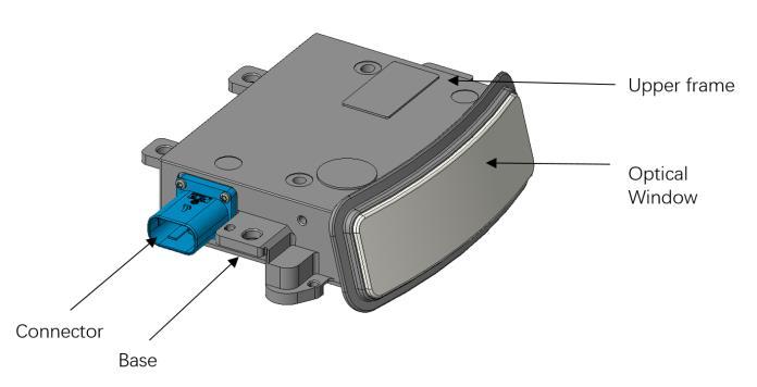
Figure 1. Product Structure of EMX LiDAR (Unit: mm)
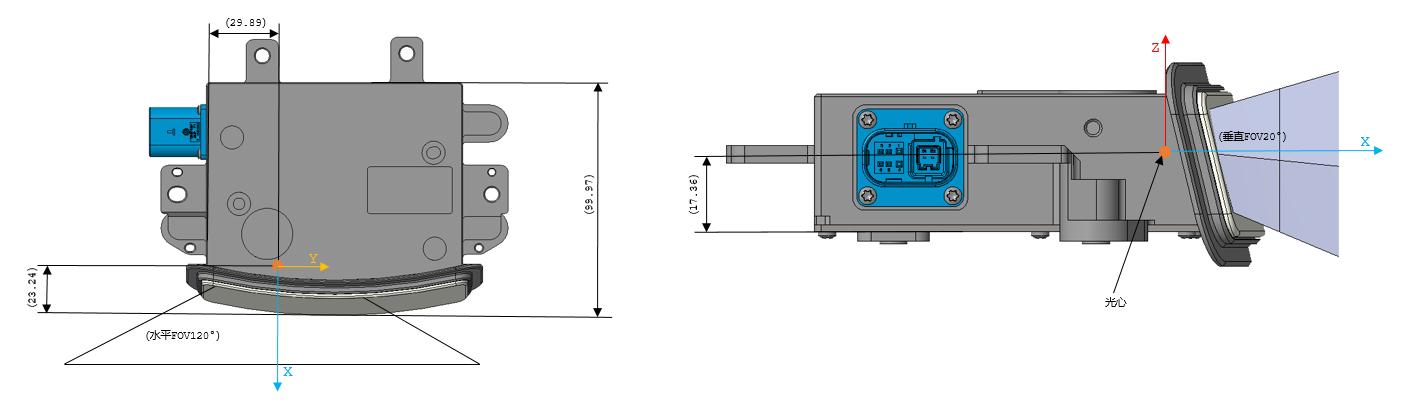
Figure 2. Position of the Coordinate Origin (Unit: mm)
2.3 Specifications
Table 1. EMX Specifications
| Sensor | |||
|---|---|---|---|
| Measurement Range1 | 1.5m to 200m (200m@10%NIST) | Accuracy2 (Typical) | ±5 cm@1σ |
| Horizontal FOV | 120° (-60° ~ +60°) | Horizontal Resolution | 0.08° |
| Vertical FOV | 20° (-12° ~ +8°) | Vertical Resolution | 0.1° |
| Frame Rate | 10 Hz | Blind Zone | ≤1.5m |
| Output | |||
| Ethernet Output | 1000Base-T1 | ||
| Output Data Protocol | UDP packets over Ethernet | ||
| LiDAR Data Packet Contents | 3D spatial coordinates, reflection intensity, timestamps | ||
| Number of Points Output | 2,880,000 pts/s | ||
| Point Output Transmission Bandwidth | 97.4Mbps | ||
| Mechanical/Electronic Operation | |||
| Operating Voltage | 9V~16VDC | Dimension(L*W*H) | Depth: 102.5mm Width: 110mm Height: 30.4mm |
| Power Consumption | 10W | Operating temperature | -40°C ~ +85°C |
| Weight | 500g ± 20g (excluding data cable) | Storage temperature | -40°C ~ +105°C |
| Time Synchronization | gPTP (Default) PTP | Protection level | IP67/IP6K9K |
| Wake-up Method | 1-pin hard-line wake-up (provides 0-2V low level for Lidar sleep mode, 7-12V high level for Lidar wake-up) | ||
1 The test is conducted using a 10% NIST diffuse reflectance target. The results may be affected by environmental factors, including but not limited to ambient temperature, light intensity, etc.
2 The test is conducted using a 90% NIST diffuse reflectance target. The results may be affected by environmental factors, including but not limited to ambient temperature, target distance, etc.
3 Product Installation
3.1 Mechanical Installation
The LiDAR Installation Schematic is shown in Figure 3.
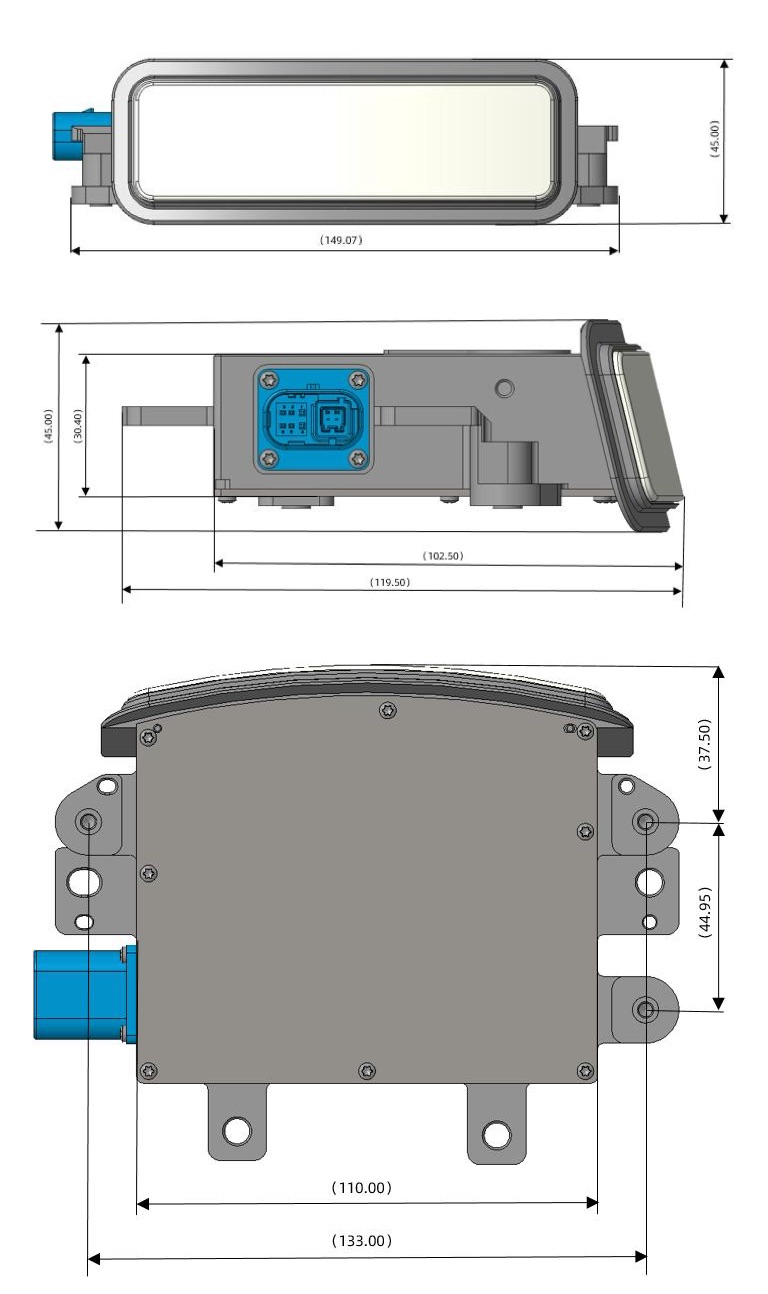
Figure 3. LiDAR Installation Schematic
3.2 Lidar Wiring and Interface Description
3.2.1 Vehicle Ethernet Cable Harness Interface and Definitions
EMX uses one automotive Ethernet and power supply two in one connector, and the matching wiring harness is shown in Figure 4.
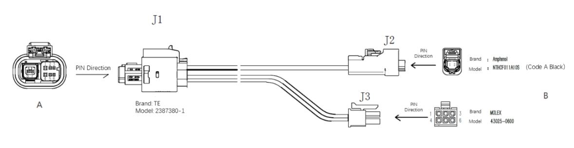
Figure 4. Vehicle Ethernet Power Cable Harness
The definitions of EMX vehicle Ethernet power harness connectors and pins are shown in Table 2.
Table 2. Vehicle Ethernet Power Cable Harness Interface Definitions
| A Side | Definition | B Side | ||
|---|---|---|---|---|
| J1 (TE 2387380-1) |
1 | GND | J3 (Molex 43025-0600) |
1 |
| 2 | Wakeup | 6 | ||
| 3 | / | 3 | ||
| 4 | Baterry+ | 2 | ||
| 5 | / | 4 | ||
| 6 | / | 5 | ||
| 7 | 1000BASE-T1 N | J2 (Amphenol NTHCF011A10S) |
1 | |
| 8 | 1000BASE-T1 P | 2 | ||
3.2.2 Interface Box
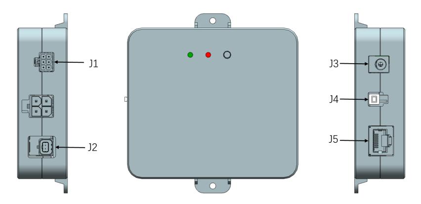
Figure 5. Interface Box
The EMX interface box has a power indicator and various interfaces, as shown in Figure 5, which can be connected to power input and RJ45 network port.
Table 3. LiDAR Interface Box Definitions
| Interface | Interface Name | Function Description |
|---|---|---|
| J1 | MOLEX 43045-0600 | Provide power to the Lidar and output wake-up signals |
| J2 | Amphenol NTBM11R1U01110T | 1000BASE-T1 vehicle Ethernet interface |
| J3 | DC Power connector | Power input |
| J4 | Switch | Wake up signal control switch, when the switch is pressed, the wake-up signal is turned on |
| J5 | RJ45 | 1000BASE-TX Industrial Ethernet |
3.2.3 Power interface
The EMX interface box uses a standard DC 5.5-2.1 power connector. When the power is properly connected, the green indicator light on the power box will remain on. If the green indicator light is off, please check the power input. If the power input is normal and the indicator light is still off, the interface box may be damaged. Please contact RoboSense for support.
3.2.4 RJ45 Ethernet port
The EMX only support 1000BASE-T1 in-vehicle Ethernet. The interface box supports
only Gigabit Ethernet and uses a standard RJ45 connector for network interfaces.
3.3 Quick Connection
The EMX network parameters are configurable, with the factory default set to a fixed IP and port mode. For details, refer to Table 4.
Table 4. Factory Default Network Configuration
| equipment | IP address | MSOP package slogan |
DIFOP packet slogan |
|---|---|---|---|
| EMX | 192.168.1.200 | 6699 | 7788 |
| PC | 192.168.1.102 |
When using the product, the user needs to set the computer's IP address to be on the same subnet as the product. For example, set the IP to 192.168.1.x (where x ranges from 1 to 254) with a subnet mask of 255.255.255.0.
If the product's network configuration is unknown, connect to the product and use Wireshark to capture and analyze the output packets. The IP configuration and connection method are as follows.
-
Connect the LiDAR
The connection method is shown in Figure 6.
- The LiDAR is connected to the interface box via an in-vehicle Ethernet power cable harness;
- The PC is connected to the interface box using Gigabit Industrial Ethernet through an RJ45 connector;
- After powering on, under normal operation, the green indicator light on the LiDAR's interface box will remain lit. For the location of the indicator light, refer to Figure 6.
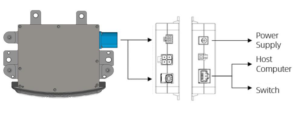
Figure 6. Schematic Diagram for Interface Box Connection
-
Configure local IP by analyzing ARP packets using Wireshark:
- After connecting the LiDAR to the PC as described in the previous steps, launch Wireshark (a third-party network analysis tool), select the correct network interface, and start capturing packets;
- In Wireshark's search bar, input "ARP" to filter and search for address resolution packets exchanged between the LiDAR and the PC, as shown in Figure 7;
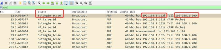
Figure 7. Analyzing ARP Messages
- As shown in Figure 7, the term "SutengIn" in the Source column indicates the information source of the LiDAR. This suggests that the Source IP is 192.168.1.200, which is the IP address of the LiDAR. Next, request access to 192.168.1.102, which is the PC's IP address. If the local IP is different from the requested IP, configure the PC's local IP to 192.168.1.102. For detailed instructions, refer to Step 3. If access is successful, proceed to Step 4.
-
Configure the local IP of the PC
- In the Control Panel, navigate to "Network and Internet" and then to "Network and Sharing Center." In the "View your active networks" section, click on the corresponding Ethernet connection to access the "Ethernet Status" page. Click on "Properties" to configure the settings;
- Double-click on Internet Protocol Version 4 (TCP/IPv4) to enter IP information settings and configure using a static IP;
- Set the local IP address to 192.168.1.102 and the subnet mask to 255.255.255.0. Click "OK" to complete the static IP configuration for the PC.
-
Connection completed
Note
- The time synchronization module (PTP & gPTP) is not included as a standard feature. If you need to use this functionality, please purchase it separately and connect it as shown in Figure 6.
- The above steps for configuring a local static IP are provided as an example for Windows systems. Please refer to the specific instructions for other operating systems.
- The EMX uses a static ARP list and only sends ARP packets after the LiDAR is powered on and before it is connected to the host computer. If the host computer is replaced after the LiDAR and the original host were communicating normally, the LiDAR must be powered off and on again to communicate with the new host computer.
4 Product usage
4.1 Product Coordinate System
The coordinate system of the product is shown in Figure 8.
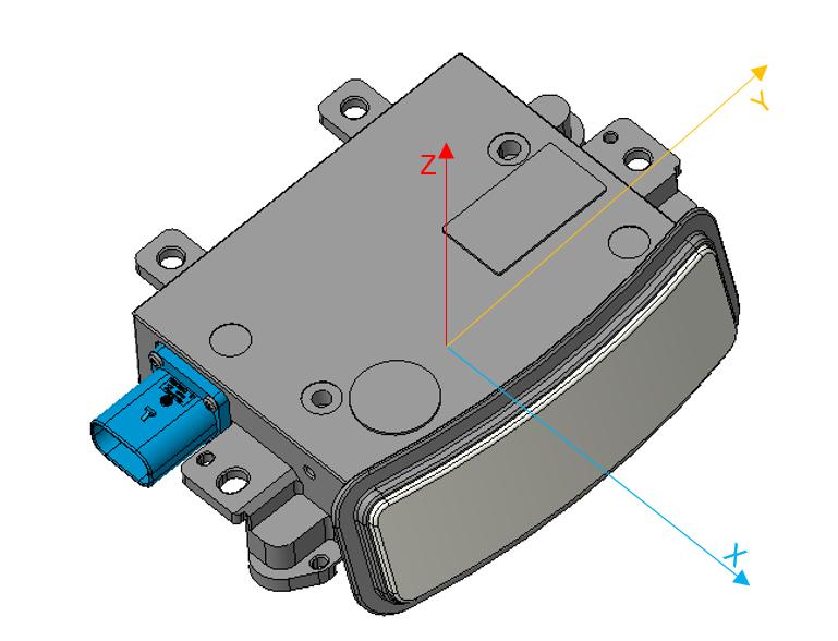
Figure 8. Schematic diagram of LiDAR coordinates
Note
The coordinate origin of the LiDAR is defined at the optical center of the LiDAR.
4.2 RSView Usage
For detecting data from the EMX, free tools such as Wireshark and tcpdump can be used to obtain raw data. RSView provides a more convenient way for users to visualize the raw data.
4.2.1 Software Functions
RSView provides real-time visualization of EMX data. It can also replay data saved in .pcap file format, but currently does not support .pcapng file format.
RSView displays the distance measurements obtained from the EMX as individual points and supports various custom colors to represent data such as reflection intensity, time, distance, horizontal angle, and laser beam number. The displayed data can be exported and saved as .csv files, and versions of RSView from 3.1.3 onwards support exporting data in .las format.
RSView includes the following functions:
- Real-time data display via Ethernet.
- Recording real-time data and saving it as PCAP files.
- Playback from recorded PCAP files.
- Various visualization modes, such as distance, time, horizontal angle, etc.
- Displaying point data in tabular format.
- Exporting point cloud data as CSV files.
- Distance measurement tool.
- Simultaneous display of multiple frames from replay data.
- Displaying or hiding individual beams (channels) in the EMX.
- Clipping display.
4.2.2 Installing RSView
RSView supports running on Windows 64-bit and Ubuntu 18.04 and above operating systems.
The extraction path for the software should not contain any Chinese characters. The software does not require installation; simply run the executable file after extraction to use it.
4.2.3 Using RSView
After opening RSView, you can access the software user guide by pressing the F1 key, or by selecting "RS-LiDAR User Guide" from the Help option in the software menu bar.
4.3 Communication Protocol
The communication between the EMX and the computer uses Ethernet medium and UDP protocol. The communication protocols between the EMX and the computer are mainly divided into two categories. For details, see Table 5.
Table 5. List of Product Agreements
| (Protocol/Package) Name | Abbreviation | Function | Type | Package Size |
|---|---|---|---|---|
| Main data Stream Output Protocol | MSOP | Scan data output | UDP | 812 bytes |
| Device Information Output Protocol | DIFOP | Product information output | UDP | 256 bytes |
- Section 4.3.2 of the product manual describes and defines the payload (812 bytes) in the protocol.
- The Main Data Stream Output Protocol (MSOP) packages and outputs information such as distance, angle, and reflection intensity measured by the LiDAR.
- The Product Information Output Protocol (DIFOP) outputs various configuration details of the LiDAR's current status.
4.3.1 MSOP & DIFOP
The UDP protocol issued by the EMX has a payload of 812 bytes. The data structures for the Main Data Stream (MSOP) and Product Information (DIFOP) are shown in Figure 9.
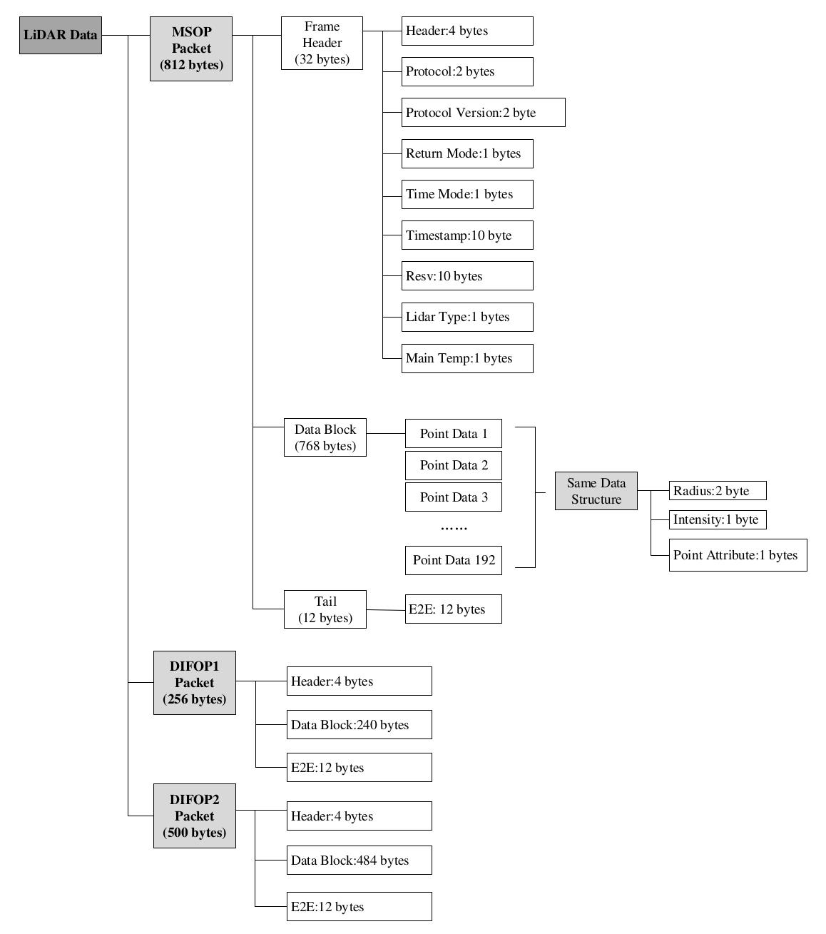
Figure 9. Schematic Diagram of LiDAR Data Structure
4.3.2 Main Data Stream Output Protocol (MSOP)
Main Data Stream Output Protocol: MSOP (Main data Stream Output Protocol).
I/O Type: Device output, computer parsing.
The default port number is 6699.
4.3.2.1 Frame Header
The Frame Header is 32 bytes long and is used to identify the start of the data. For details on the data structure, refer to Table 6.
Table 6. MSOP Header Data Table
| Frame Header (32 bytes) | |||
|---|---|---|---|
| Field | Offset | Length (byte) | Description |
| Header ID | 0 | 4 | 4 bytes are used for packet header detection, defined as 0x55, 0xAA, 0x5A, 0xA5。 |
| Pkt_cnt | 4 | 2 | Counts the packets, with the count starting at 1 for the beginning of each frame and reaching the maximum value at the end of the last point of each frame. Each frame contains a total of 1520 packets. |
| Protocal version | 6 | 2 | Indicates the version of the UDP communication protocol. |
| Return_mode | 8 | 1 |
Indicates the current point cloud echo mode of the device: 0B0000-double Echo 0B0100 - Strongest Echo 0B0101 - Last Echo 0B0110 - Nearest Echo |
| Time_mode | 9 | 1 |
Indicates the current time synchronization mode of the device: 0B00 - Internal radar timing 0B10 - PTP Time Synchronization 0B11 - GPTP Time Synchronization |
| Timestamp | 10 | 10 | Timestamp: The first 6 bytes represent seconds, and the last 4 bytes represent microseconds. |
| Reserved | 20 | 10 | Reserved |
| LiDAR Type | 30 | 1 | Default value is 0x42 |
| Main Temp | 31 | 1 | Device Temperature: Temp = Device_Temp - 80, where an original value of 0 represents -80°C, and 255 represents 175°C. |
4.3.2.2 Data Block Interval
As shown in Table 7, the Data Block section is the measurement value portion of the MSOP packet, totaling 768 bytes. It consists of 192 Point Data, each 4 bytes in length, representing a complete set of distance measurement data.
Detailed definitions are as follow:
Table 7. Data Block Packet Definition
| Data Block N (4 Bytes) | |||
|---|---|---|---|
| Field | Offset | Length (byte) | Definition Explanation |
| radius | 0 | 2 | Radial distance value in polar coordinates, with a distance resolution of 5 mm. |
| intensity | 2 | 1 | The reflection intensity values for radial points, ranging from 0 to 255 |
| point_attribute | 3 | 1 |
point_attribute: 0x01:normal point 0x02:noise point |
4.3.2.3 Frame Tail
The Frame Tail (Tail) is 12 bytes long, reserved for checksum and counting.
4.3.3 Device Info Output Protocol (DIFOP)
Device Info Output Protocol, abbreviated as DIFOP.
I/O Type: Output from the device, read by computers.
Default Port Number: 7788.
DIFOP is an "output-only" protocol to periodically send the LiDAR serial number (S/N), firmware version information, host computer driver compatibility information, network configuration information, calibration information, operating status, and fault diagnosis information to users. By reading DIFOP, users can learn specific information of various parameters of the LiDAR currently in use.
The data format structure of a complete DIFOP packet consists of a frame header and a data area. Each data packet is 256 bytes in total. The basic structure of the data packet is shown in the table below.
Table 8. DIFOP Definition
| DIFOP1 256Byte | |||
|---|---|---|---|
| Catalogue | Offset | Byte | Definition |
| StatusHdr | 0 | 4 | A5 FF 00 5A |
| Reserved | 4 | 20 | |
| SWVersion | 24 | 3 | |
| HWVersion | 27 | 2 | Default:B0 |
| Reserved | 29 | 6 | |
| CustomerSN | 35 | 16 | 0xF18C |
| WorkMode | 51 | 1 |
0x01: Init 0x02: Wait_Normal 0x03: Pre_Reset 0x04: Post_Reset 0x05: Standby 0x06: Pre_Sleep 0x07: Post_Sleep 0x08: Fault 0x0A: Normal others: Reserved |
| FrameRate | 52 | 1 | 0x0A:10Hz 0x14: 20Hz |
| WaveMode | 53 | 1 |
0x00:NearestFarthestWave 0x04:StrongestWave 0x05:FarthestWave 0x06:NearestWave 0x0A:Hist 0x0B:Gray |
| ROIMode | 54 | 1 | |
| CalibrationMode | 55 | 1 | 0x00: Normal mode 0x01: Factory mode |
| WindowBlockageStatus | 56 | 1 | |
| WindowBlockageLevel | 57 | 18 | |
| Reserved | 75 | 14 | |
| TimesyncMode | 89 | 1 |
0x00: internal Src timer 0x01: PPS timer 0x02: E2E L2 timer 0x03: gPTP timer 0x04: p2p L4 timer |
| TimesyncStatus | 90 | 1 | 0x00: failed 0x01: Success 0x02: Timeout |
| TimeStamp | 91 | 10 | 0-5 bytes: Second 6-9 bytes: MicroSecond |
| PhyMasterSlaveMode | 101 | 1 |
0x00: auto-negotiation 0x01: master 0x02: slave other: same as 0x00 |
| SrcIP | 102 | 4 | Default:C0 A8 01 C8 |
| NetMask | 106 | 4 | Default:FF FF FF 00 |
| MacAddress | 110 | 6 | Default:08-48-57-00-FB-93 |
| MsopDstIp | 116 | 4 | Default:C0 A8 01 66 |
| MsopSrcPort | 120 | 2 | Default:1A 2B |
| MsopDstPort | 122 | 2 | Default:1A 2B |
| Difop1DstIp | 124 | 4 | Default:C0 A8 01 66 |
| Difop1SrcPort | 128 | 2 | Default:1E 6C |
| Difop1DstPort | 130 | 2 | Default:1E 6C |
| Reserved | 132 | 24 | |
| TMON6_WIN | 156 | 1 | (hex to dec) -100 °C |
| TMON8_FPGA | 157 | 1 | (hex to dec) -100 °C |
| Reserved | 158 | 71 | |
| LidarFunctionFault | 229 | 1 | |
| ExtPowerSupplyFault | 230 | 1 | |
| CommFault | 231 | 2 | |
| FaultLevel | 233 | 1 |
0x00: No fault 0x01: FL1 0x02: FL2 0x03: FL3 |
| FaultID | 234 | 2 | |
| FaultValue | 236 | 4 | |
| DTCList | 240 | 4 | |
| E2E | 244 | 12 | |
| DIFOP2 500Byte | |||
|---|---|---|---|
| Catalogue | Offset | Byte | Definition |
| InfoHdr | 0 | 4 | A5 FF 00 AE |
| Res0 | 4 | 63 | |
| SurfaceCnt | 67 | 1 | there are 2 scan direction: clockwise and anti-clockwise |
| VcselPixelCnt | 68 | 1 | 1 vcsel:8 pixel |
| VcselCnt | 69 | 1 | 1 column:24 vcsel |
| VcselYawOffset | 70 | 24 |
factor:1/512 1 vcsel:8 pixel 1 column:192 pixel: 24 vcsel |
| PixelPitch[1~192] | 94 | 384 | channel 1 pitch: factor:0.005; range:-2416~1595 ->-12.08~8.08; Unit: deg |
| SurfacePitchOffset | 478 | 4 |
There are 2 surface byte[0:1] clockwise byte[2:3] anti-clockwise |
| RollOffset | 482 | 2 | factor:0.01 |
| Res1 | 484 | 4 | |
| E2E | 488 | 12 | |
5 Fault diagnosis
This chapter lists some common problems encountered during the use of the product and corresponding troubleshooting methods. Please refer to Table 8 for details.
Table 8. Common Troubleshooting Methods
| Fault phenomenon | resolvent |
|---|---|
| The red/green indicator light on the interface box is not on/flashing | Check if the connection wire between the interface box and the power end is loose; Check if the wiring harness is damaged. |
| The product keeps restarting during startup |
Check if the input power connection and polarity are normal; Check whether the voltage and current of the input power supply meet the requirements (under the condition of 12V voltage input, the input current is ≥0.833A); |
| Wireshark can receive data, but RSView does not display point clouds |
Turn off the computer firewall and run RSView to pass through the firewall; Confirm that the IP configuration of the computer matches the destination address set for the product; Confirm that the Sensor Network Configuration setting in RSView is correct; Confirm that the RSView installation directory or configuration file storage directory does not contain any Chinese characters; Confirm that the received packet in Wireshark is of MSOP type. |
| Frequent data loss of products |
Confirm whether there are a large number of other network packets or network conflicts in the network; Confirm whether there are other network products in the network that are sending large amounts of data in broadcast mode, causing sensor data blockage; Confirm whether the performance and interface performance of the computer meet the requirements; Remove all other network products and connect directly to the computer to confirm if there is any packet loss. |
| Unable to synchronize gPTP time |
Confirm whether the radar firmware matches the required synchronization mode; In gPTP time synchronization mode: Confirm whether the gPTP Master synchronization protocol complies with the current gPTP protocol; Confirm if gPTP Master is working properly. |
| The product has no data output after passing through the router | Turn off the DHCP function of the router or set the sensor's IP address to the correct IP address inside the router. |
6 Product maintenance
6.1 Transportation and Logistics
Improper transportation can cause product damage
- The product should be packaged with shockproof and moisture-proof materials to avoid damage during transportation. It is recommended to use the original packaging;
- Handle with care during transportation to avoid impact or dropping;
- When receiving the goods, carefully check the delivery list for any damages (including the product and packaging);
- If there is any transportation damage, refuse to accept the delivery and contact RoboSense promptly.
6.2 Storage
Improper storage may cause product damage
- Store the product in an indoor environment with normal temperature and dry conditions;
- Handle the product gently to avoid impact or dropping;
- The product should be stored in a safe environment to avoid corrosion, mechanical impact, or exposure to environments exceeding the protection level;
- Regularly inspect the condition of all components and packaging, and it is recommended to check every three months.
6.3 Product Cleaning
To ensure accurate perception of the surrounding environment, keep the RS-LiDAR's circular protective cover clean.
6.3.1 Precautions
Note
- Before cleaning the RS-LiDAR, carefully read and understand the content of this section. Improper cleaning may damage the product.
- When using the LiDAR in harsh environmental conditions, clean the surface regularly to keep the LiDAR clean. Otherwise, it may affect the normal operation of the LiDAR.
6.3.2 Required Materials
- Clean and dust-free cloth;
- Neutral solution at moderate temperature (such as soapy water, distilled water, 99% concentration of ethanol, etc.).
6.3.3 Cleaning Method
-
If the LiDAR surface is only covered with some dust:
- Use a clean and dust-free cloth, dip it in a small amount of neutral solution;
- Gently wipe the LiDAR surface;
- Dry it with a clean and dry dust-free cloth.
-
If the LiDAR surface is covered with mud or other solid foreign objects:
- First, spray clean water on the dirty part of the LiDAR surface to remove the mud or foreign objects (Note: Do not directly wipe off the mud with a dust-free cloth, as it may scratch the surface, especially the protective cover);
- Then spray warm soapy water on the dirty part. The lubricating effect of the soapy water helps to remove the foreign objects. Gently wipe the LiDAR surface with a fiber cloth, but be careful not to scratch the surface;
- Finally, rinse off the residual soap on the LiDAR surface with clean water (if there is still residue, clean it again with 99% ethanol) and dry it with a clean and dry dust-free cloth.
7 After sales
If the solutions provided in Chapter 6 of the troubleshooting guide do not solve the problem, please promptly contact RoboSense.
Official Website: https://www.robosense.cn/en/contact
Email: support@robosense.cn
Phone: +86-0755-86325830 / +86-15338772453
Info
- Please wait for a confirmation response from RoboSense after-sales service before sending the product back;
- When sending the product back, please use the original packaging or an equivalent cushioned and moisture-resistant packaging.
Appendix A: TE Connector Pin Definitions
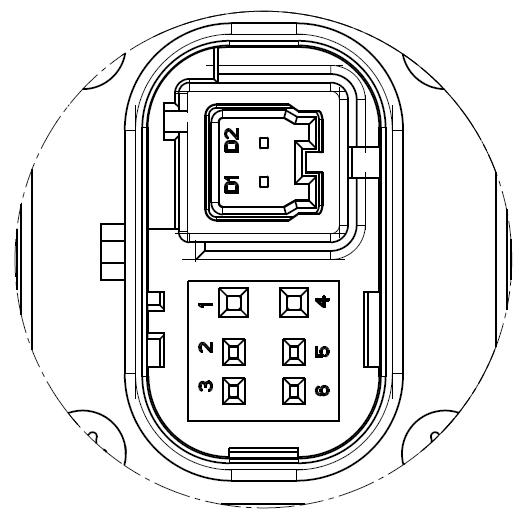
| Pin No | Pin Definition | Connector Model Number |
|---|---|---|
| 1 | GND | TE 2387351-1 |
| 2 | Wakeup (KL15) | |
| 3 | / | |
| 4 | Battery+ | |
| 5 | / | |
| 6 | / | |
| D1 | TRX_N (1000Base-T1) | |
| D2 | TRX_P (1000Base-T1) |